Simple doorbell detection and remote triggering using ESPHome
sound sensor reverse engineering esp32 esphome homeassistant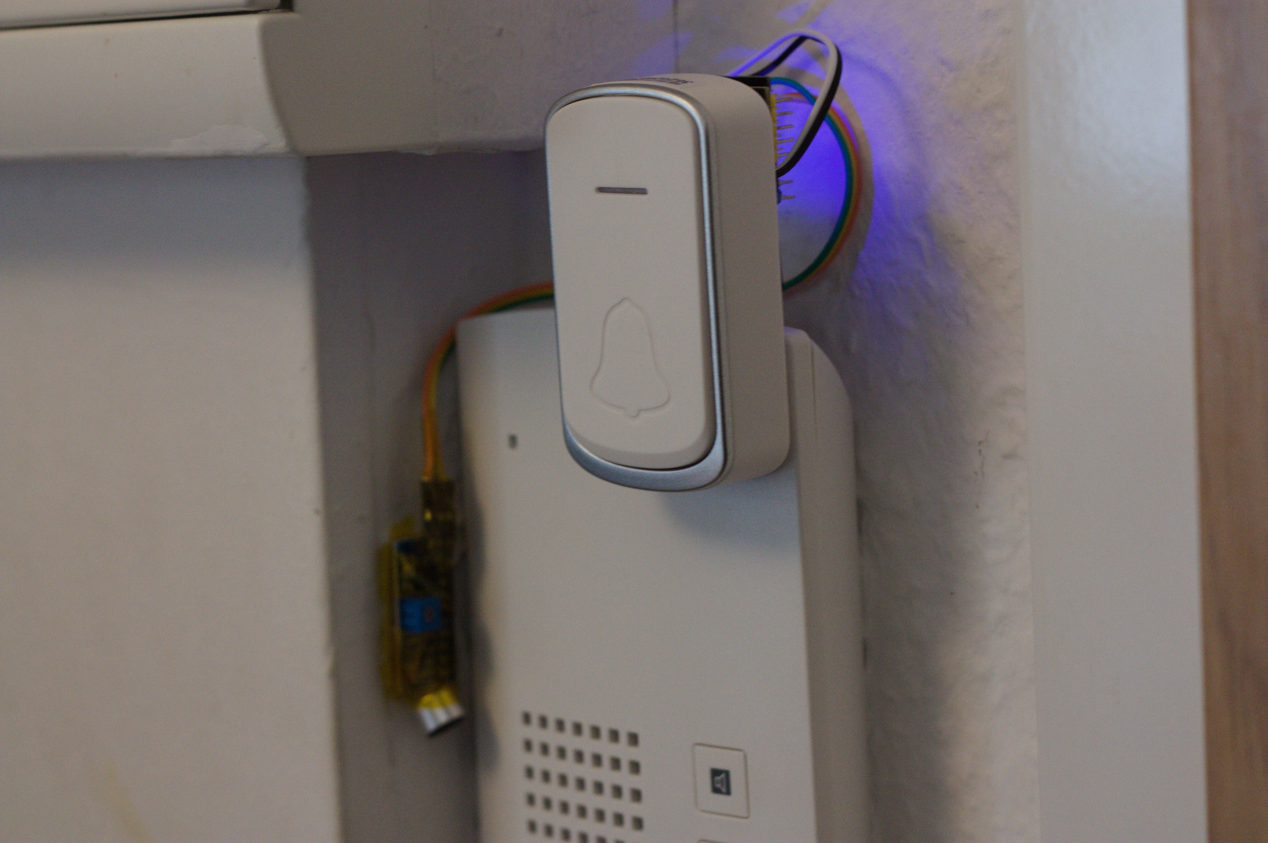
Intro #
This project uses an ESP32 and ESPHome to enhance a traditional analog-ish door phone by detecting when it rings and triggering a secondary visual alert that one can see in other rooms. The setup integrates smoothly with HomeAssistant, so you also get a log showing when someone rang.
The setup is non-invasive (i.e., without opening your doorbell), which was important in my case because I don’t have access to the central unit's control cabinet.
As a bonus, you can also configure the ESP32’s built-in LED as a notification light in HomeAssistant. I configured mine to turn on with the entrance lights, so I know it’s running.
In this post, I’ll cover the hardware, ESPHome configuration, and integration into HomeAssistant. Note that this text is an extensively revised version of the README.md of the project repository, based on my lab notes, which were formatted and cleaned up a bit by GPT-4o.
Design #
My custom hardware is relatively simple, it consists of:
- 1x ESP32-C3 SuperMini (Reference)
- 1x PC817 optocoupler
- 1x Sound trigger sensor (possibly similar to: KY-037)
And hacked parts:
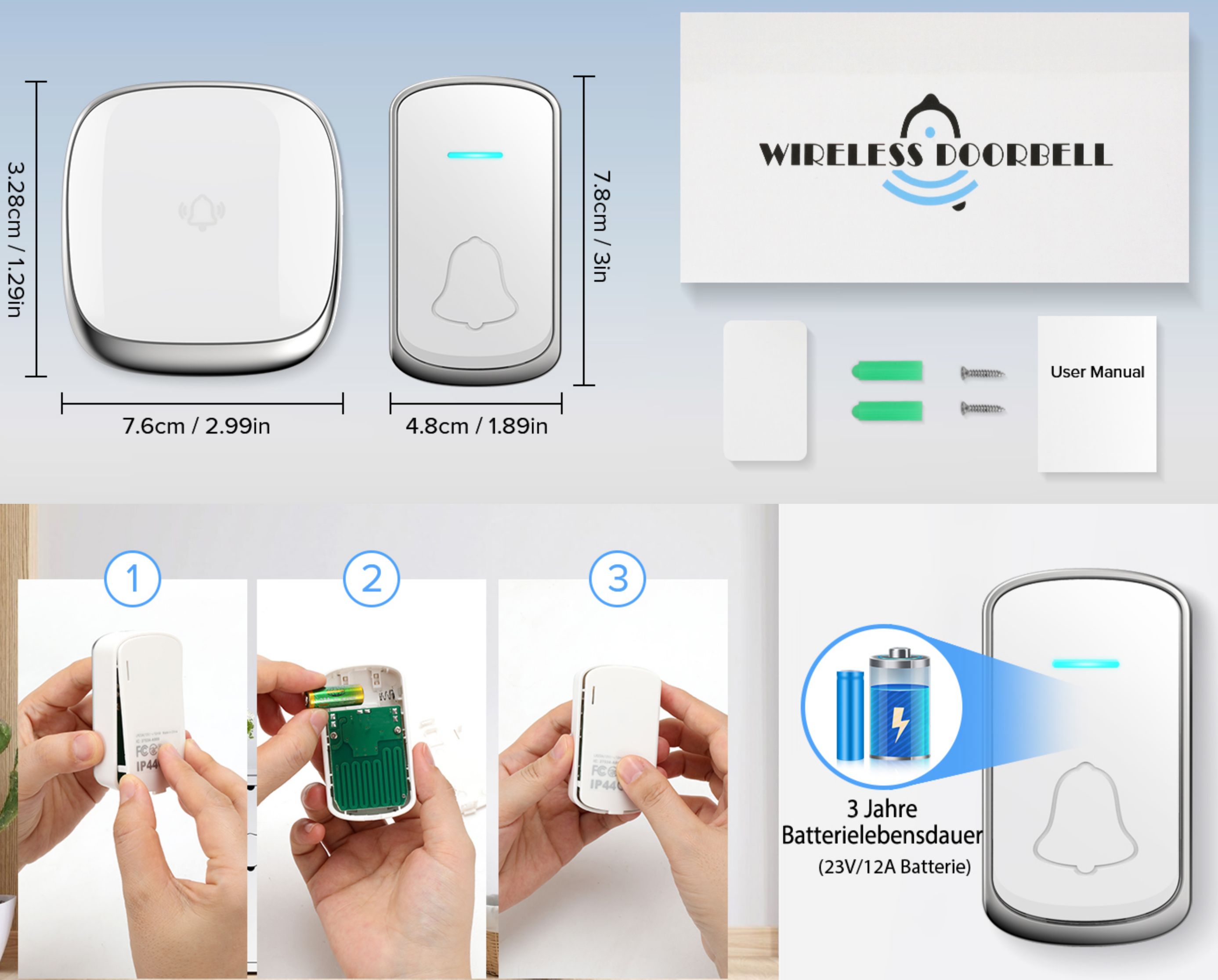
- Wireless Doorbell Set "B209": 433 MHz remote + 2 wall units:
Schematic #
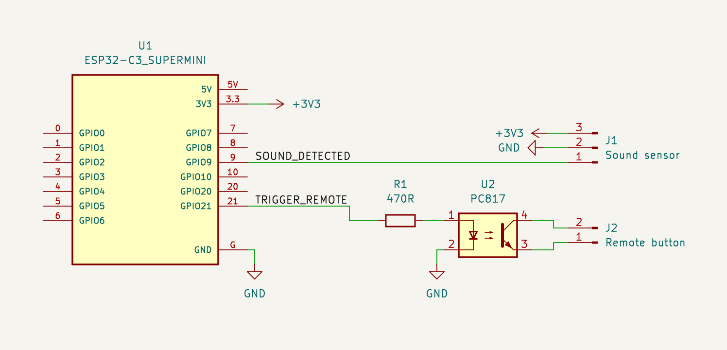
The circuit we need to build is quite basic: 1 input, 1 output:
- Input: We get a binary signal from the sound detector, which is logical low as long as sound above a certain threshold is detected
- Output: We simulate a simple button push by making the photo-transistor conduct for a certain time, so that the remote is triggered reliably
- Processing: This task is ideally suited for the ESPHome framework and its nice built-in filtering and debounce capabilities; also it makes HomeAssistant integration a breeze.
Design considerations:
- the ESP32 shall trigger an event for HomeAssistant when it's loud enough (our primary audible doorbell rings)
- we can trigger the remote of the secondary (visual) doorbell, either from the "sound detected" interrupt handler or via an external event from HomeAssistant
- The remote runs from a small 12 V battery (A23). Its button connects a normally pulled down input signal to +12V, therefore we need something to deal with a voltage the ESP32 can't switch directly. I chose to add the optocoupler to deal with this because it's easy to use.
- The optocoupler's transistor, if active, connects the two sides of the push button of the remote together.
Sound Sensor (excursion) #
Let's dive a bit more into the sound sensor to make this project more interesting. As it turns out its design is quite common but I didn't know that at first so maybe you enjoy my take on it.
Central to the circuit is an LM393 comparator for thresholding the detected amplitude. My usual workflow is to 1. make some carefully aligned photos, 2. import them as layers into GIMP, 3. trace and annotate the PCB on different layers. This is the preliminary result:
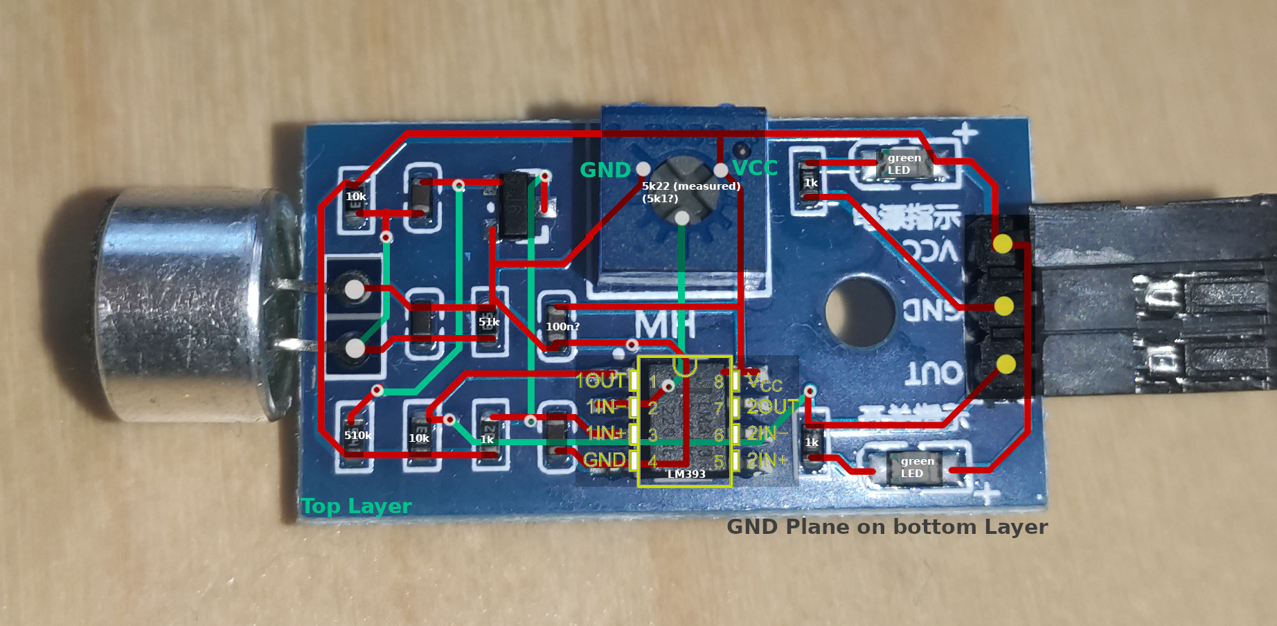
From that I reverse-engineered the schematic on pen and paper and created a schematic in KiCad (LEDs, second channel of LM393, and supply omitted):
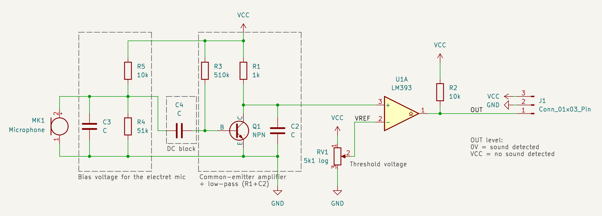
Now we can make sense of it in a structured way (see schematic, from left to right):
- Sound enters our electret microphone capsule -- the capsule needs a bias voltage to operate which is supplied by a resistor divider (R4, R5)
- The signal now has a steady DC component and an additional AC component on top of that when sound is captured
- That signal's DC component gets blocked by C4 to center it again around 0 Volts
- An amplifier stage brings the signal into a manageable range for the comparator. It's built around a common-emitter amplifier with an NPN transistor (similar to MMS9014 (datasheet))
- additionally, R1 and C2 seem to form a low-pass filter to get rid of higher frequencies (this should be at least below the bandwidth of the comparator)
- The comparator LM393 (datasheet) compares the conditioned signal amplitude with the threshold voltage set by the potentiometer. Note the pot seems to use a non-linear, possibly logarithmic scale to make it easier to adjust (it's still pretty finicky though, maybe this could be improved -- how cool would it be to use the ESP32's DAC to set the trigger level dynamically?)
- The output (
OUT) signal is pulled high by default, but driven low when sufficiently high amplitude (= sound at the capsule) is detected. - The green LED near the output lights up when
OUTis low. (The other LED is just always on and I removed it later to save power.)
So finally, we get a digital signal that we can handle easily in almost any microcontroller.
I like this approach because with a simple hardware circuit we get functionality similar to physical privacy shutters on webcams which thankfully have become increasingly wide-spread: By design it's not possible for the software on the ESP32 to be repurposed for recording sound. Well, I'm not too concerned about that but nevertheless I think this synergy between hardware and software to provide additional security is pretty cool. It's like writing elegant software.
Prototype #
Version 1 #
So for the first prototype I just grabbed the smallest ESP32 board I could find -- I think I paid around 3€ each for the ESP32 board and its expansion board on AliExpress.
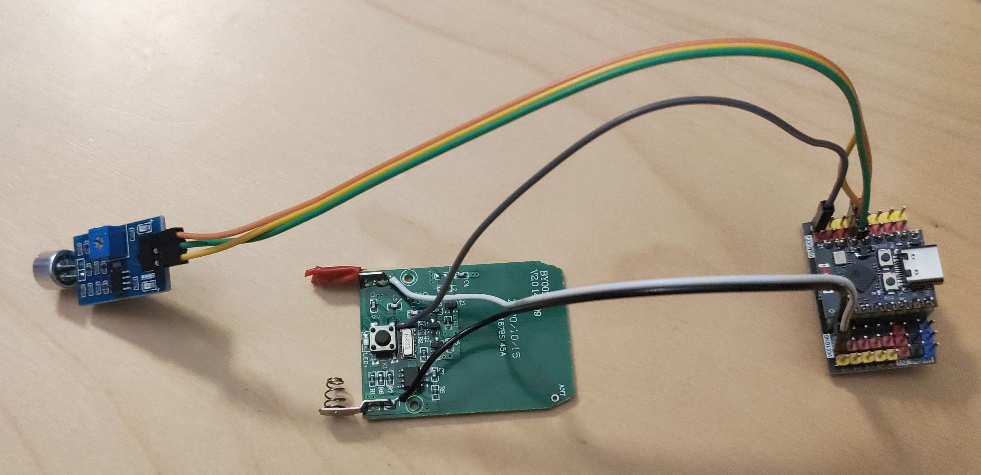
Our ESP32 and sound sensor are powered by the ESP32 board's 3.3 V regulator. That regulator is powered by 5 V from the USB-C port. The sensor doesn't use much power so this should be sufficient.
You might have noticed that there is no optocoupler yet in this version. I deliberately tried supplying the remote with 3.3 V instead of 12 V from the battery, since I expected a wide input voltage range on that radio IC. It seemed to work at first but triggering the wall wart chimes wasn't as reliable as with 12 V.
Version 2 #
The second iteration of the prototype is what you saw on the title image and the schematic. I basically just connected the PC817 optocoupler (DIP-4 package) with wires to the button's pins and to the ESP32 and "shoved" it into the case, dead bug style.
Software #
Of course, this project has a software component, too. Check out the project repository at https://github.com/spezifisch/esphome-entry/ if you are interested or want to build something similar. You will find additional information at the end of the README.md which I omitted here for brevity.
Operation (Pseudo-Summary) #
This device has been running for 5 days now from an old 20 Ah USB Powerbank (which was full initially and now shows half full) and sound detection as well as logging in HomeAssistant worked reliably when someone rang, but it had a false positive when someone shut the entrance door too loudly. To mitigate this I increased the volume of my (primary) doorbell and re-adjusted the trigger threshold. Now you have to slam the door pretty hard to get a false positive.
Surprisingly, this old powerbank from Anker doesn't switch off the output power under whatever low load this circuit produces.
Going Further #
Instead of a full summary let's imagine how we could improve this project:
- The LM393 comparator has an unused channel. Maybe we could add a second output signal with a different threshold or even with a low-passed or band-passed input signal that removes frequencies that are irrelevant for our doorbell detection. This might suppress false positives more robustly.
- Power consumption on the ESP32 could probably be reduced by using ESPHome's deep sleep functionality
- I'm not sure whether ESPHome is using interrupts or is polling the input pin. This should be checked to ensure it's using interrupts which should use less power.
That's it. Have a nice day!
- Previous: PSV3 Soldering Iron Hack - Part 2