Govee RGB Strip (H619A) Part 1 - Investigation
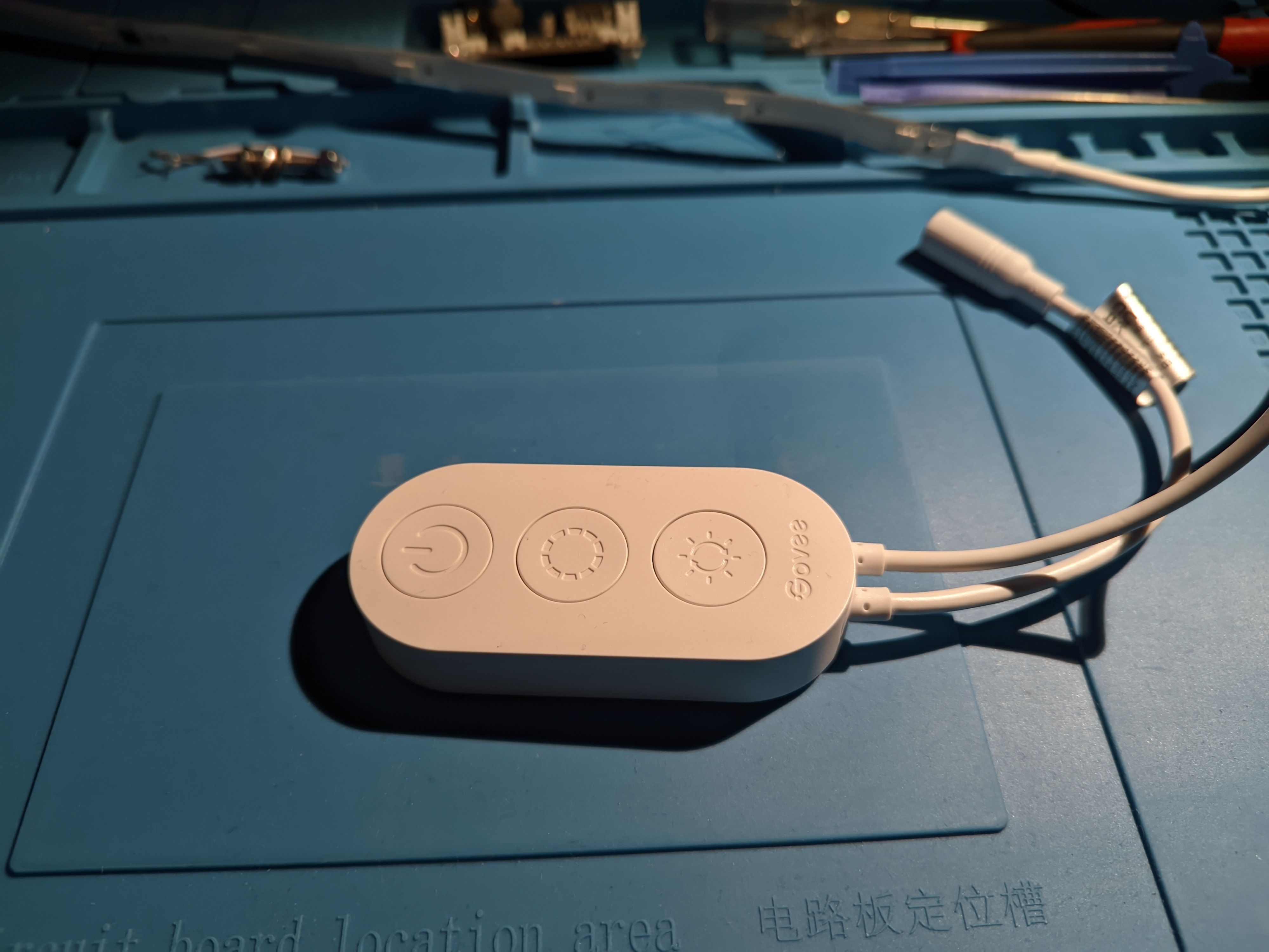
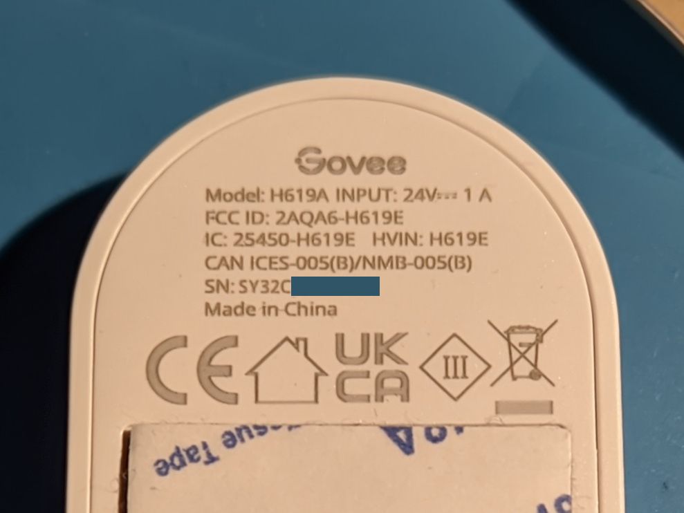
reverse engineering lightI recently got a Govee H619A RGB LED strip. It is 5 meters long and its LEDs are grouped into segments which can be controlled individually. The main components are a controller box with 3 buttons, a 24V/1A wall wart, and the strip itself. The strip is divided into 20 segments with 6 RGB LEDs each. And of course there is a mobile app for remote control.
TLDR: The RGB strip is controlled with the WS2812 protocol using 5V logic level and 24V supply. The Bluetooth and WiFi hardware is cheap closed source stuff and quite boring.
Motivation #
You control the RGB strip with the app using Bluetooth (directly) or WiFi (through cloud other people's servers).
But of course you have to create a Govee account first. Then you just enter your WiFi network key inside the app (thankfully optional though pushed onto you).
And then the thing - which also contains a microphone, did I mention? - is controllable from anywhere. Great! What could go wrong?
In any case that controller board needs to go and be replaced by something like an ESP32 with a Free firmware.
I then want to use it via HomeAssistant without the Govee Cloud API and as such without needing to trust some random company and hope that their servers are maintained forever. Well, there is the Govee Bluetooth integration but it doesn't support their RGB strips and I really don't want to go down that road working with their proprietary BLE high level protocol.
Internals #
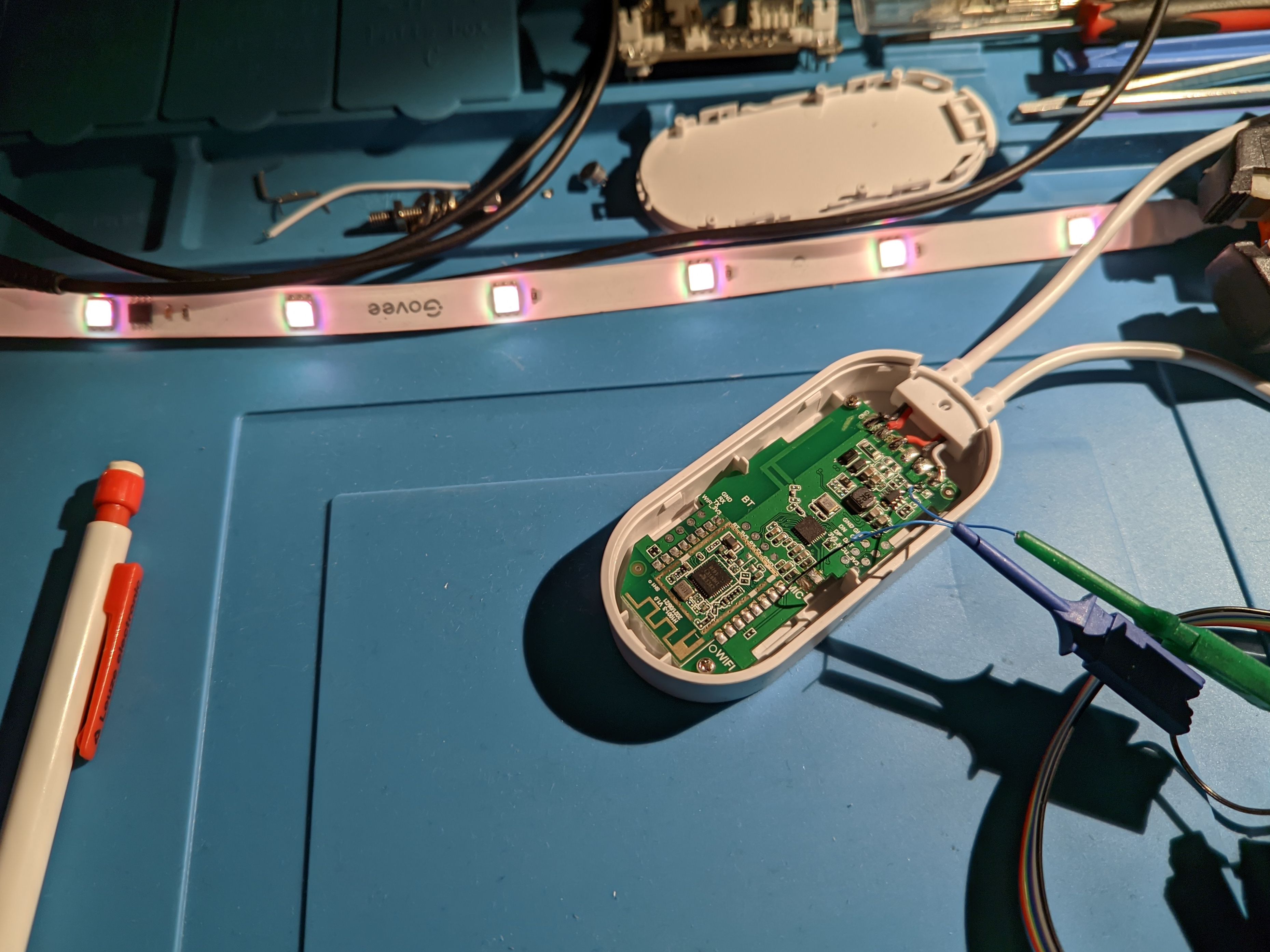
The controller is easily opened as the back plate is just clipped in place:
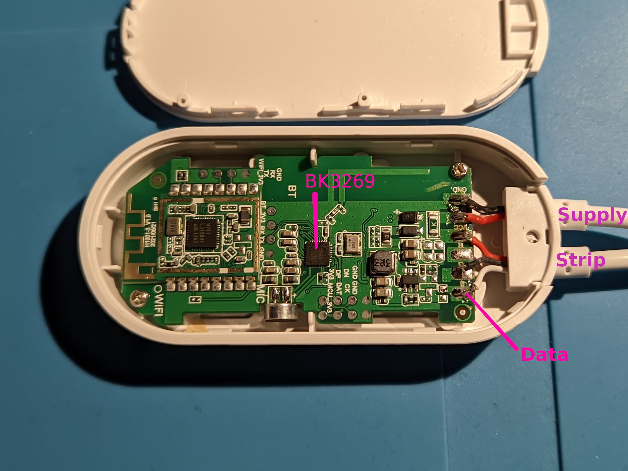
The 24V supply is connected through a high-side shunt (around 0.1 - 0.2 Ohm as far as my multimeter can measure) to the RGB strip. The ground line between supply and strip is connected directly.
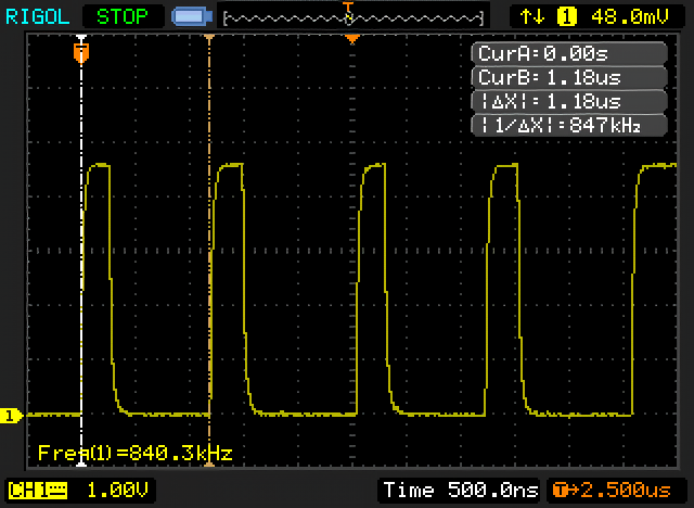
Probing around with the oscilloscope the most action happens on the data output pin (labelled in the previous image). The bit timing should be pretty easily recognized if you know about the WS2812 protocol. (I didn't.)
Other than that there is some communication on the test pads labelled RX and TX between the Bluetooth and the WiFi module when you change the LED pattern using the app.
RGB strip data output #
I hooked my fx2lafw Logic Analyzer to the data pin and captured some communication. The signal is quite fast so you need a sample rate on the upper end of what the analyzer supports (16 MHz gives good results).

Every 20 ms there is a burst of bits. Occasionally there is a longer delay though.

I added the WS281x protocol decoder in PulseView for the screenshot so you can already see the color values for the individual segments of the strip. Here all segments except for the 18th are off and the other one is showing a dimmed white.
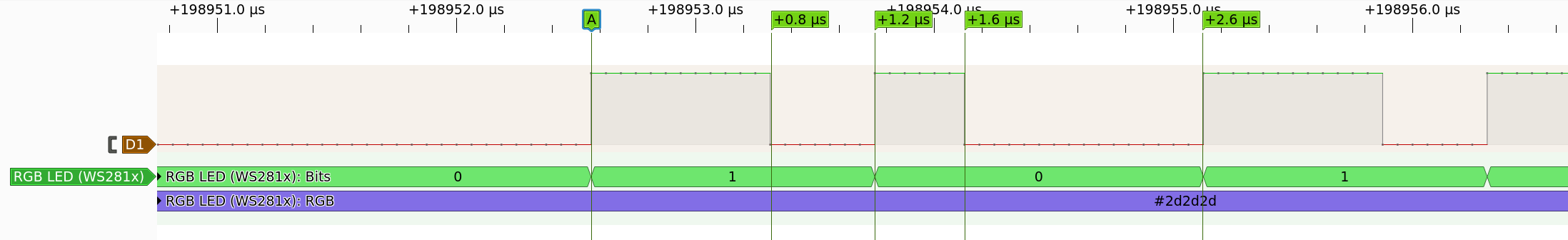
At this point I saw what looked like On-Off keying and it dawned on me that this might be the WS2812 (or rather WS281x, I guess) protocol so I looked it up and sure enough the bit timing matched within tolerance (0.8 µs high, 0.4 µs low; and 0.4 µs high, 1 µs low). And then I finally found its protocol decoder is already included in PulseView.
Compare the measured timings to the WS2812B datasheet:

Funnily enough, once I knew what protocol I was looking for I searched online for "govee ws2812" and I found a Reddit thread from Sep. 2020 with photos of WS2811 ICs in a Govee light.
Side note: Bluetooth SoC #
The Bluetooth SoC is a Beken Corporation BK3269. The nearest thing Beken have on their website is the product description of the BK3266 which is described as a device for audio applications.
It's connected to the microphone, the 3 front buttons, the RGB strip, and the WiFi module.
Side note: WiFi module #
The WiFi module seems to play only an auxiliary role. From a quick check with the oscilloscope it seems to be talking with the Bluetooth SoC using 3.3V level UART.
According to the FCC documents the WiFi controller should be a Realtek RTL8720CF (datasheet available here) which is also shown in the internal photos in FCC document 5627324.pdf (p. 4) with the correct markings on the chip, containing the crab and all. But this doesn't match the markings on my model which are W701 L3198I.