Pokemon Go Plus autocatcher DIY
esp32 freecadThis is a post about the software and hardware side of my recent project, building a mobile device that works like a Pokemon Go Plus with extra features. It is based on an Yohanes' ESP32 implementation of its protocol which uses the results of the reverse engineering efforts done by several people since 2017.
TLDR: My fork of pgpemu is released under BSD-3-Clause license. My 3D printable case is available at my pgpemu-case repository with its FreeCAD sources under CC BY-NC-SA 4.0. This post is based on my READMEs for those repositories.
A Short History #
The Pokemon Go Plus (support page) was released in 2016 and its selling point was basically that you can play a mobile game without looking at a mobile phone. It is a low power Bluetooth LE device that operates from a coin cell. You pair it with your Pokemon Go app on your phone and then it vibrates and blinks when an in-game action can be taken. You then have to react manually by pressing a button.
To avoid having to press that button some people built clips that just always press it or just tied a coin with some rubber band to the device to achieve the same. Others wired the vibration motor output to the button so it presses itself automatically.
Meanwhile compatible devices cropped up like Datel/Codejunkies' Go-tcha series which can automatically simulate a button press. They emulate a Go Plus on their own custom hardware with extra features.
Also notable are a range of clone devices like the Pocket Egg/Pair which contain the same Bluetooth SoC as the original Go Plus (twice for the Pair) with the same firmware as an original. The pins which are used for button and LEDs in the original are wired to a microcontroller which then automatically presses the button for you.
Reverse Engineering #
Public reverse engineering was done by BobThePigeon_ (2017), Yohanes Nugroho (2018: one, two), and Jesus Bamford (2019) who also implemented an OTA bootloader exploit (2019) to dump a Go Plus without needing to modify its hardware.
The bottom line is that the Bluetooth connection between Pokemon Go Plus (the wearable) and Pokemon Go (the app) is authenticated with a handshake protocol using mutual challenges and responses based on shared secrets. Due to the mentioned reverse engineering efforts the protocol for this is known to the extent that you can implement it on your own hardware using pgpemu which my project is based on.
However, it is currently not known if you can generate valid secrets yourself from scratch. That's why to my knowledge every clone (like Pocket Eggs and fake Go Pluses) and every emulator (like Go-tchas and pgpemu) uses secrets dumped from a genuine Go Plus. Since the secrets seem to be tied to the wearable's MAC address, the clones and emulators have a limited set of MAC addresses or even only one each with known dumped secrets. This sharing of MAC addresses leads to some interesting issues as Yohanes already noted in his article.
Note that if the secrets can't be generated from the MAC address alone the app needs to get it from somewhere. If that is done using the usual RPC mechanism in Pokemon Go, it should be contained in their protobuf files.
I haven't disassembled any Go-tchas yet but all the hardware clones I examined shared the same MAC address but different ones for each product line.
It will be interesting to see whether the newly announced Pokemon Go Plus+ will use a new protocol. The current security mechanisms worked well enough to deter widely available/usable Open Source emulators long enough and considering that Datel will probably crack it quickly anyway, there don't need to be a lot of changes. Curiously enough the current protocol already has enough reserved bits left in their button messages to implement the new functions like throwing another type of Pokeball in a backward compatible manner.
Software #
Starting from Yohanes' latest pgpemu commit of 2020 I reworked the code quite a bit to make it more easily maintainable. My goal was to make the emulated device more realistic and harder to detect. You can read about the details in my README.
The most notable features are:
- connect up to 4 devices simultaneously
- parse LED patterns to auto-press the button only when needed
- button press delay and duration are randomized
- the handshake nonces are now randomized and saved per connected device
- serial menu to reconfigure autocatch/autospin/etc. on the fly
- secrets are saved in their own partition to make development easier
Some limitations still are:
- The battery reading is always the same value. I might add a real measurement of my battery voltage to address this.
- The ESP32 can only have one MAC address at a time. So you get problems connecting it to multiple accounts on the same phone at the same time in split screen or windowed mode.
- You need a Go Plus to dump the secrets to begin with.
Currently I'm using the button to start Bluetooth advertising when I want to connect an additional phone.
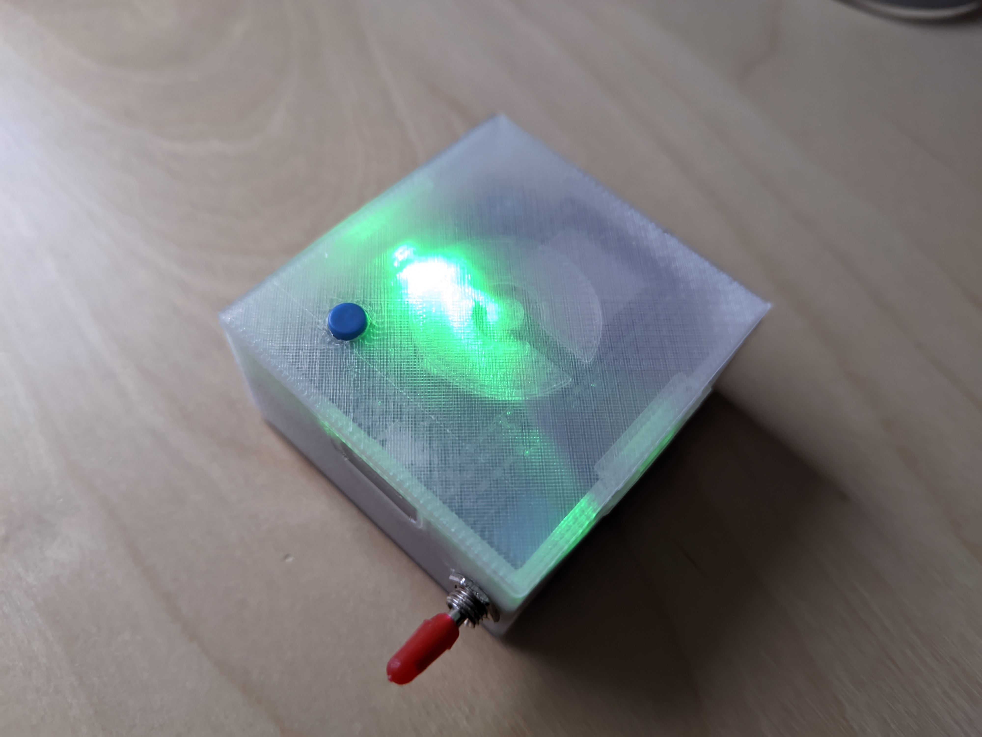
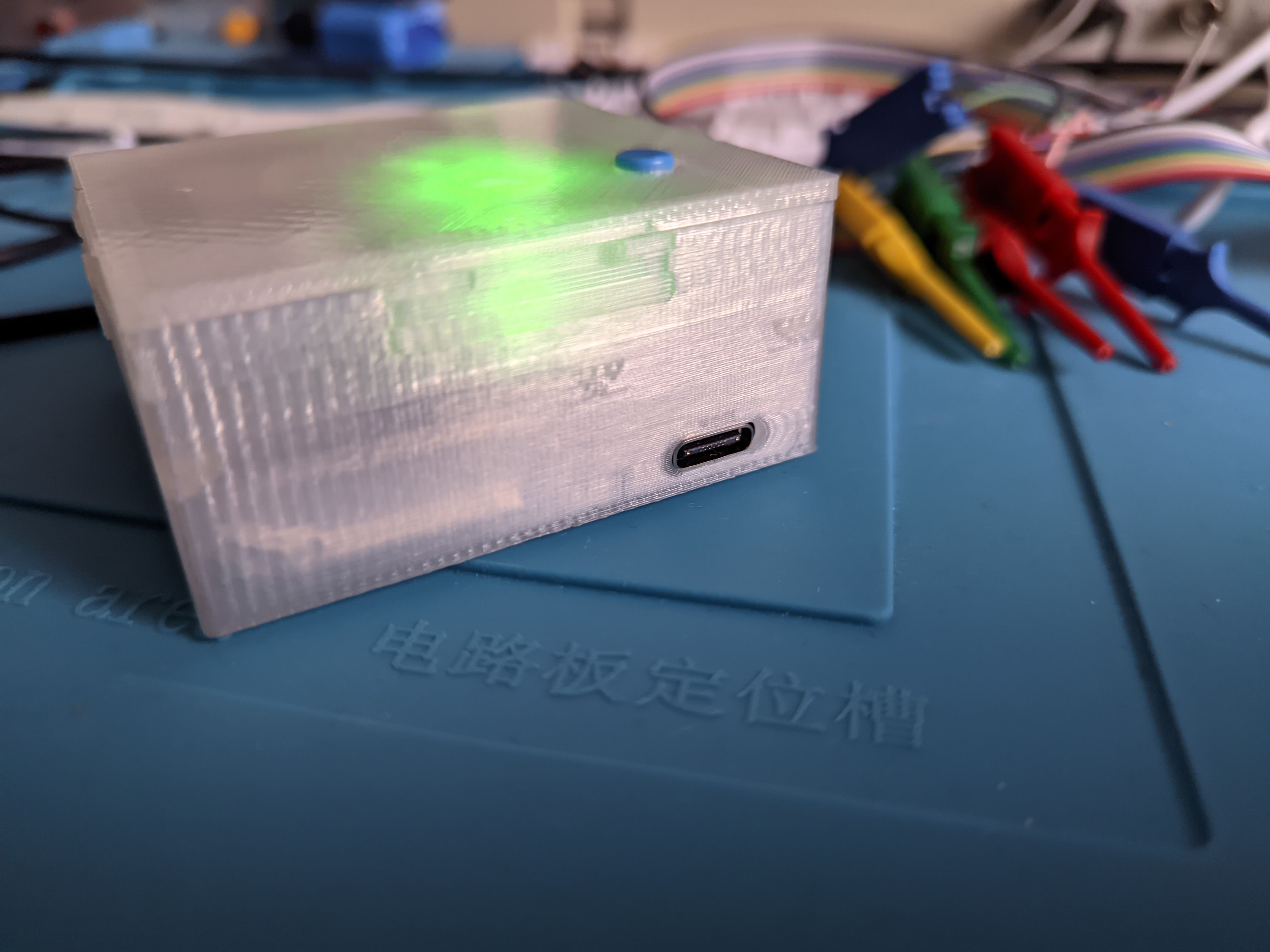
The RGB LED doesn't show the same patterns as a normal Go Plus but a simplified version which is less blinky:
- green - Pokemon was caught
- yellow - New species of Pokemon was caught
- pink - Pokemon fled
- blue - got items from Pokestop
- red - Pokemon box full or item bag full
- steady blue - Bluetooth is advertising
Electronics #
ESP32 #
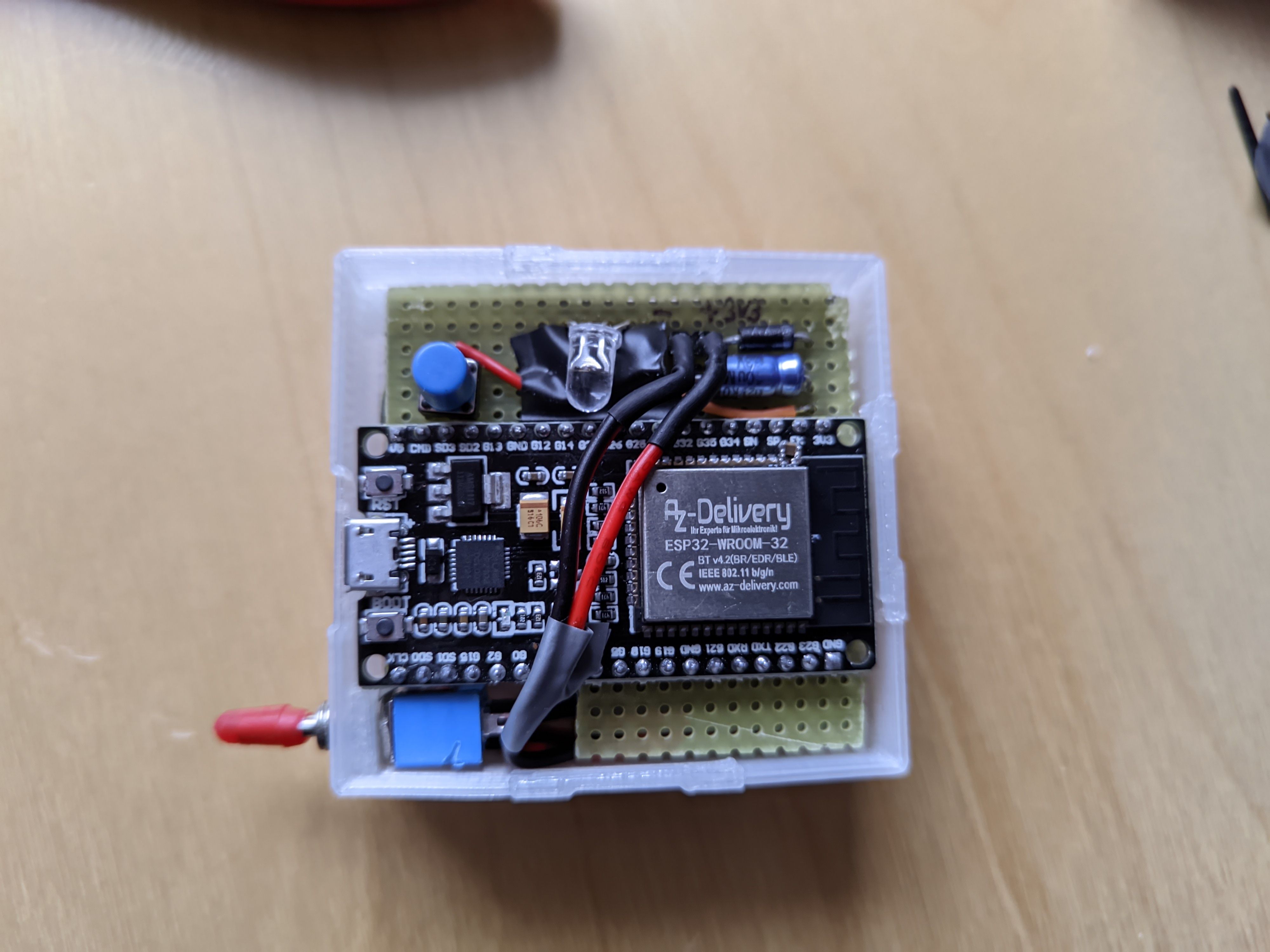
As ESP32 board I used a Devkit C compatible one I had lying around. Another choice would have been something like the DFRobot FireBeetle which already integrates a LiPo charger or a DFRobot Beetle which is way more compact.
Note that the Devkit-like boards sometimes have brownout issues due to their capacitor placement and count. I added a 0805 10µF ceramic capacitor directly to the ESP32 module like mentioned in the linked post.
LiPo Charger and Battery #
I used a TP4056 charger module with DW01A battery protection IC and a USB-C connector.
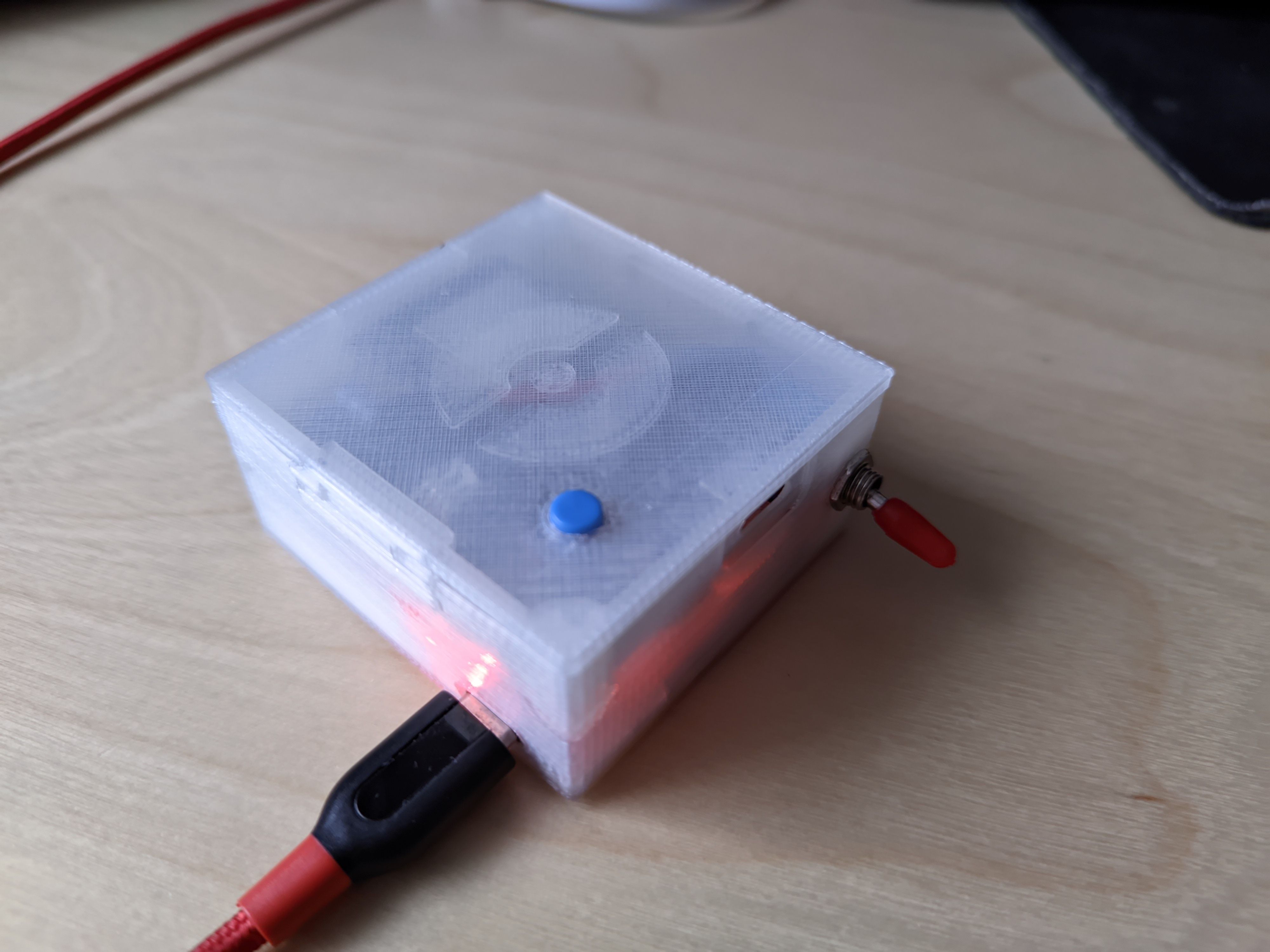
Note that TP4056s are a bit tricky to handle safely. In short, you need to disconnect any load (like the ESP32 board) when charging or it will potentially charge the battery forever, creating a fire hazard. That (and saving power) is what my toggle switch is for.
Also note that the DW01A is only providing overcurrent protection on this charger board.
In order to still make it reasonably safe I chose a 1800mAh battery with its own protection circuit which also provides overcharge and over-discharge protection I would otherwise not have safeguards against.
Another choice for battery management would have been an MCP73871-based board as described in this article.
Supply #
The ESP32 has an operating range from 3.0V - 3.6V (see datasheet p.46).
The LiPo battery that I chose has a safety circuit which ensures the voltage is >=3.0V and <=4.28V (see battery datasheet section 6.1.0) but the TP4056 charger only charges until 4.263V anyway (see TP4056 datasheet p.2). Also note that we're charging with 1A (the charger uses R_prog = 1k2 by default) and the battery supports this according to the datasheet.
Now I considered generating the ESP32's voltage using either:
- a boost regulator: battery -> boost 5V -> 3.3V with LDO on the ESP32 board -> ESP32
- a modern LDO with 0.3V dropout voltage directly: battery -> LDO 3.3V -> ESP32
- a standard silicon diode to get the battery's range into the ESP32's range: battery -> diode with 0.7V forward voltage -> ESP32
I went with the diode to reduce part count so I get between 2.3V and 3.5V which is safe for the ESP32 and it's working fine.
Note: As explained above, you can't have the device switched on while charging. However, you can connect the ESP32's Micro USB while charging with the switch in the off position. Looking at the ESP32 board schematic the AMS1117 output would be connected with your diode's cathode so you won't get backward currents into the battery or USB port.
Case #
At first I tried designing a case for my battery-powered gadget in Tinkercad. I did some light work with Tinkercad before and was amazed how well it actually works for a CAD running in your browser.
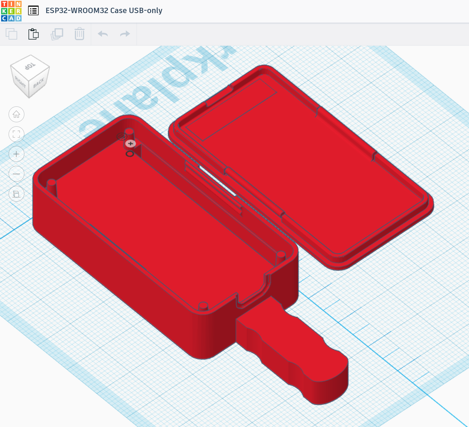
But having used SolidWorks before I was quite confused after I looked up how cumbersome it is to just split a part into two and I still can't quite wrap my head around how to align different parts on the first try.
Long story short, I went on using FreeCAD with the Assembly4 addon which after a day of adjustment provided a very familiar experience.
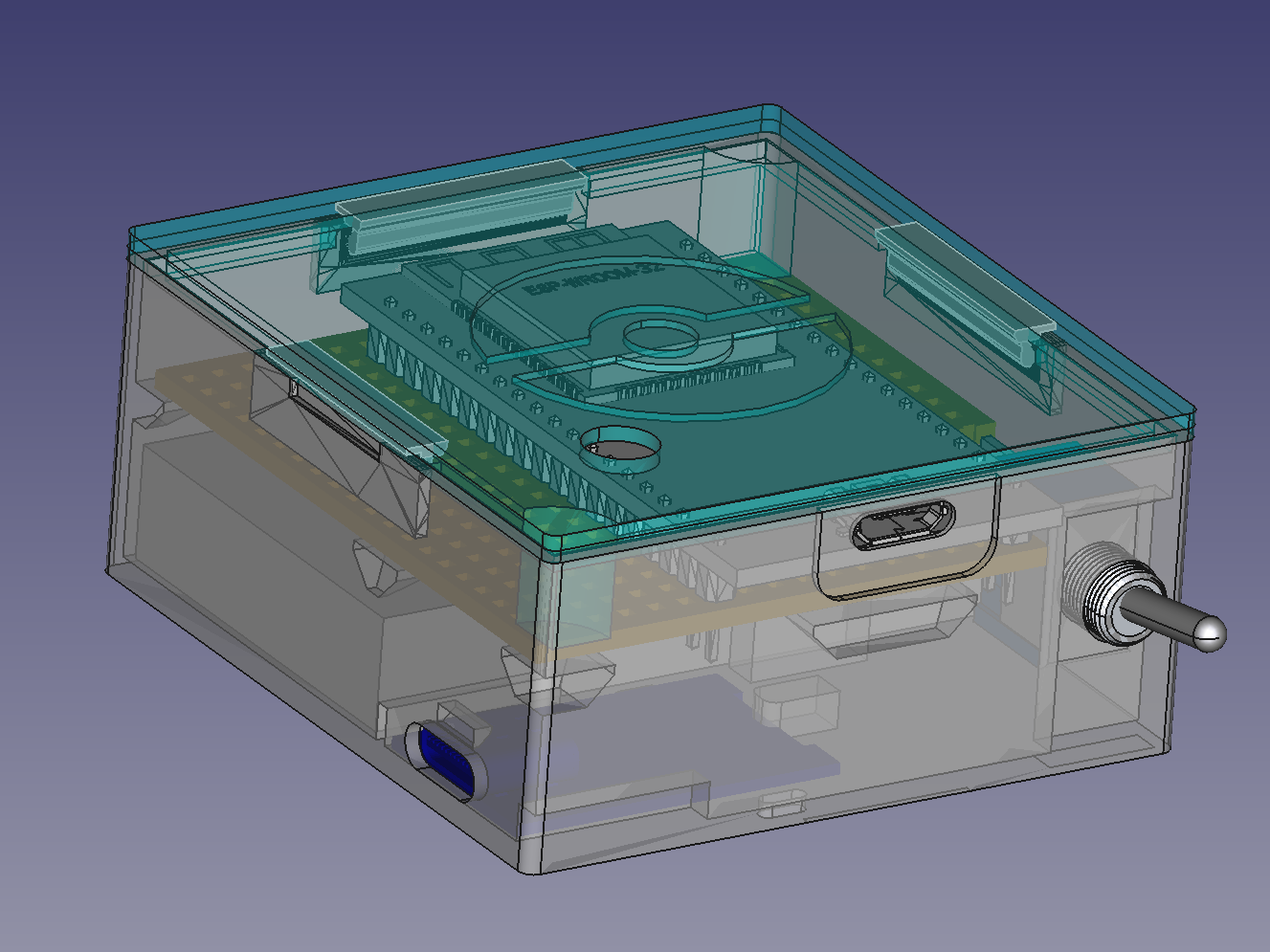
Assembly #
At the bottom the TP4056 is tied in place using a cable tie. There is a small stub above the USB-C port to keep it from going up. On the side with the cables I added a small block that keeps the charger from being pushed into the case.
The battery is glued to the bottom of the case with a small piece of double-sided adhesive tape to keep it in place. I also added a small piece of foam above the battery (not pictured) and some isolating tape covering the pointy parts of the perfboard. There should be enough space for possible LiPo bloat.
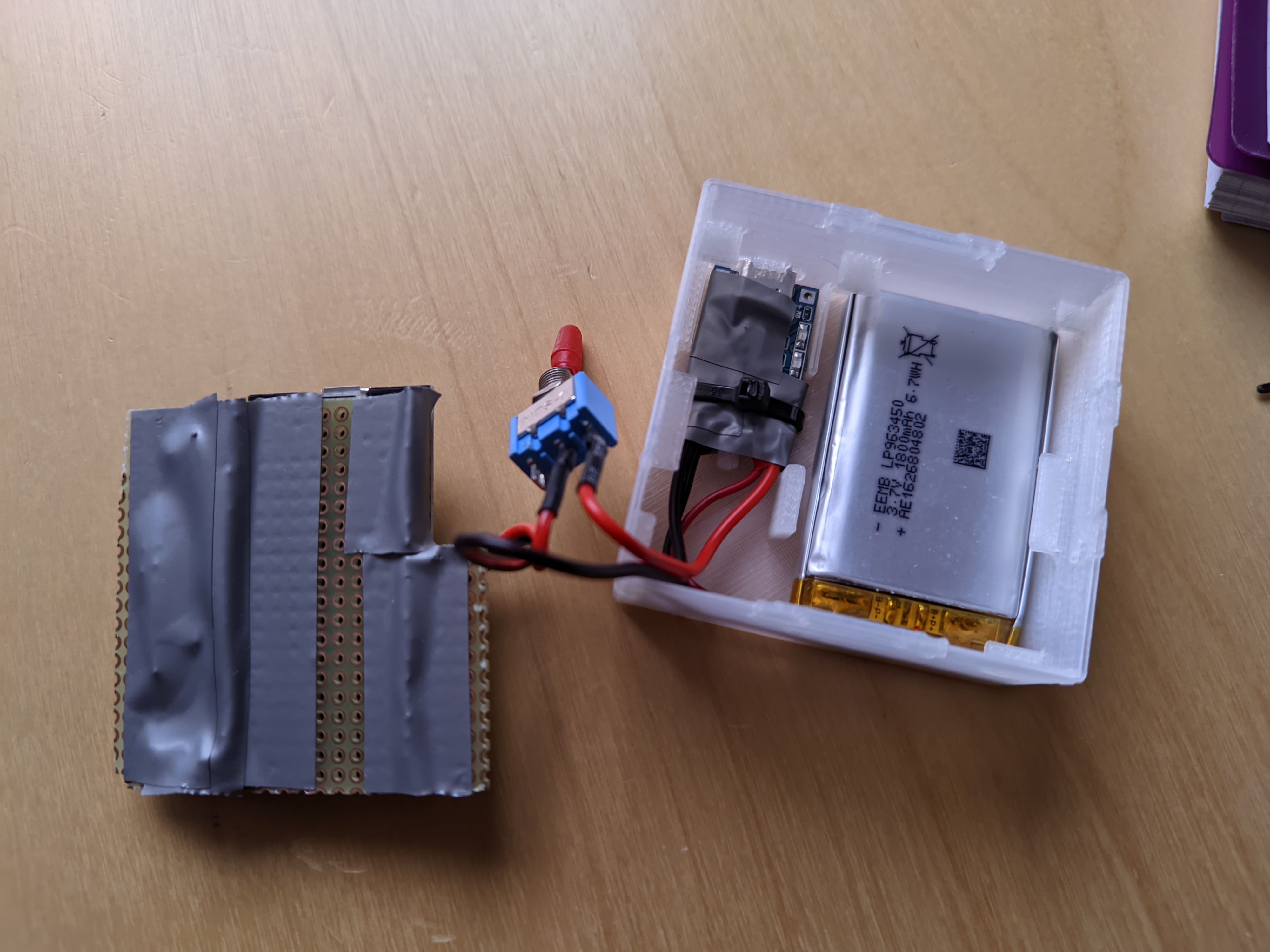
The perfboard rests on top of that on the small holders at the sides. I used 45° angles so the holders don't sag down when printing. This turned out quite well.
The lid uses a clip mechanism that I reused from the design I based my previously mentioned old case on, so the gadget can be almost fully disassembled without tools (except for the cable tie around the charger). The lid pushes down tightly on the corners of the perfboard to keep it from moving up.
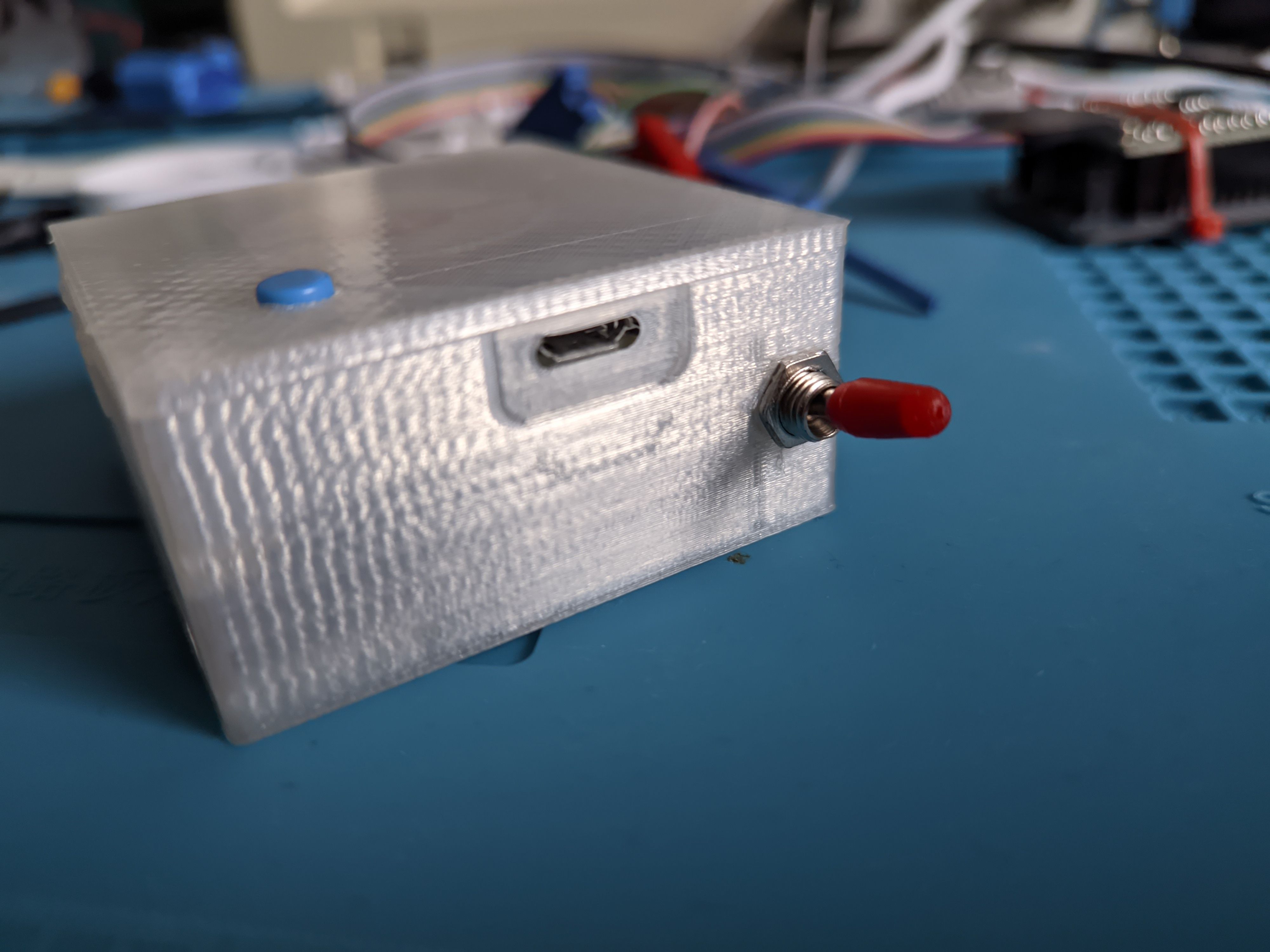
I had to pay special attention to the thin wall around the Micro USB port when printing. The wall needed to be quite thin there so plugs can fit. But my 3D printer software decided to slice away this part because the wall was thinner than the extrusion width but the "thin wall" option there remedied this problem. From now on I'll make sure to look at the slicer's output before starting the print.
There also was a recession around the charger's USB-C in my first print but I realized that it wasn't necessary because USB-C plugs seem to be longer leaving more space.
And that's it! I can now throw this device into my backpack and run around playing a mobile game without having to play it. When Pokemon Go gets old for me I will just need to grind away the Pokeball shape on the lid.