GT-ACQI-22WO digital alarm clock hack
hack clock esp32Nowadays when opening a cheap clock you will probably be greeted by the dreaded epoxy blob with a lot of traces going from it to the display or LEDs. Thankfully the designers of the Globaltronics GT-ACQI-22WO used a discrete display controller and no epoxy at all, so we have an easy starting point for our soon to be ESP32-enhanced clock! (As soon as I saw this, I went back to the store and bought the other one they had left in the clearance sale.)
Display #
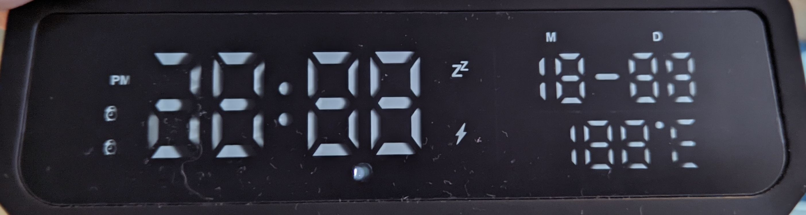
The display board named DIY-1941LED pretty much contains the whole clock: The main PCB has white LEDs on its front-facing side which
are separated by plastic dividers. They shine through a mask to form the displayed symbols and segments.
The back side of the main PCB has an unidentified sanded off microcontroller, a display controller (AIP1640), a passive buzzer, a coin cell holder to keep the RTC running, and connections from the power supply (flex cable socket) and to the button PCB (white/red cables).
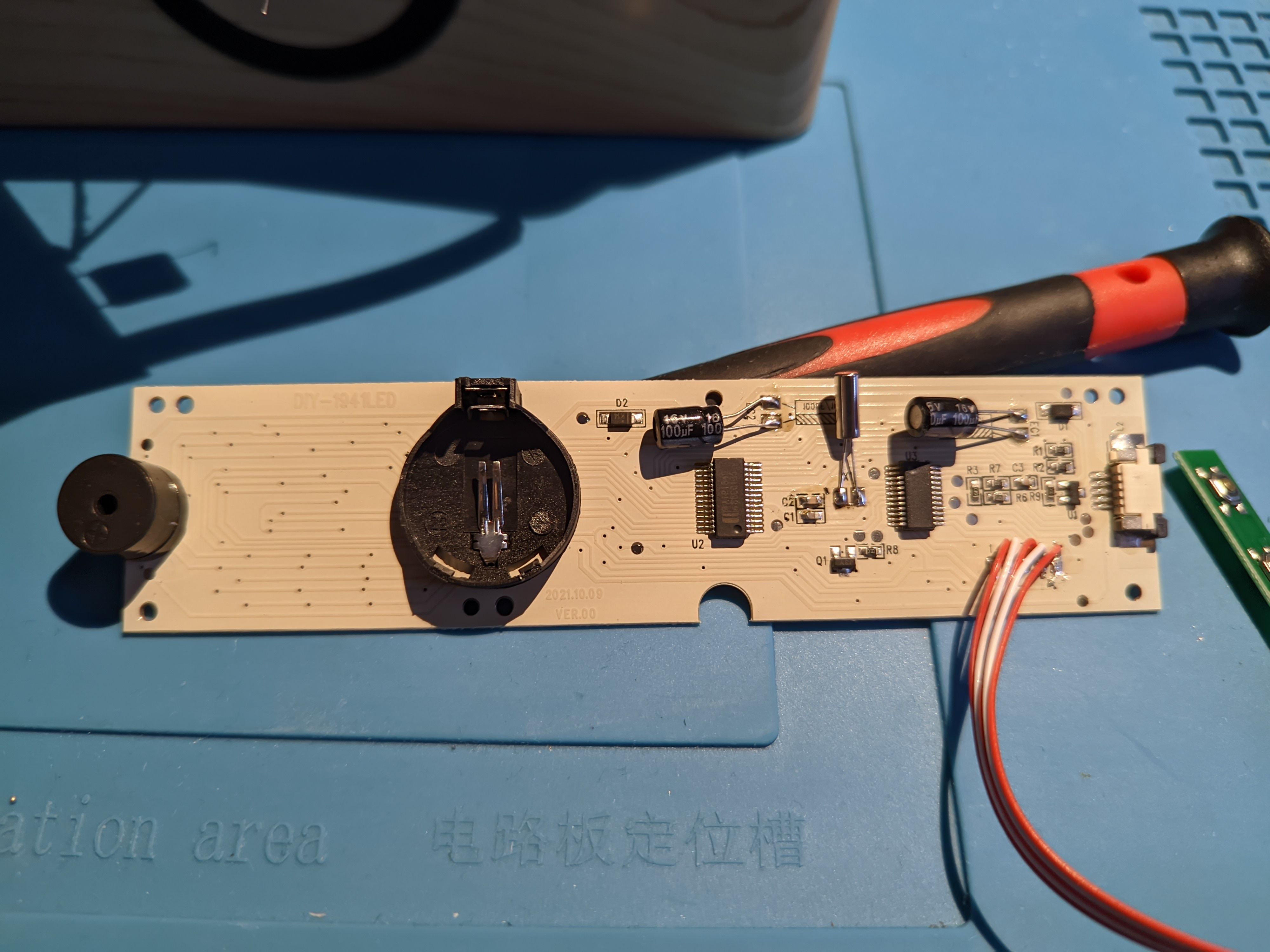
All the LEDs (except one) are connected to the display controller, which is a Wuxi I-core Elec AiP1640 (English/Chinese datasheet).
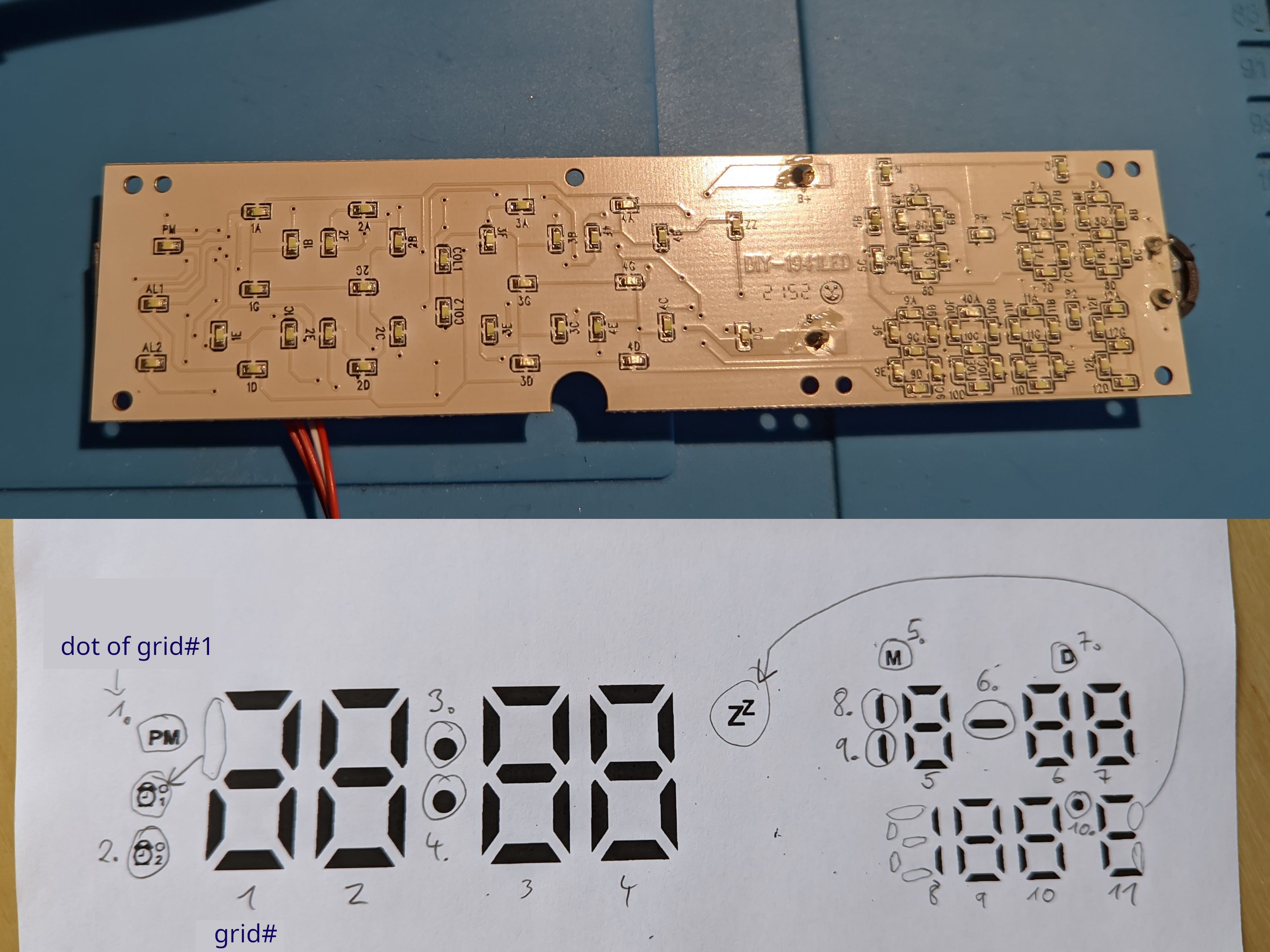
It can control up to 16 grids with 8 LEDs each (7 segments + 1 decimal dot) - on this board only the first 11 grids are used.
It has an SPI interface and luckily I read somewhere that it's compatible with the TM1640 which is pretty common and supported in some libraries. This was almost plug & play. By going through all the segments and dots in sequence (controlled by an ESP32) I got this mapping between grid/segments and the display:
I mentioned one LED before that isn't connected to the display controller. This is the status indicator of the wireless charging IC, which is a bolt symbol that is located below the "zZ" snooze indicator. The bolt LED is connected between Ground and the middle pin (labelled "LED") of the 5 pin flex cable that goes to the power supply board. Its 1 kΩ series resistor sits on the power board and I think it's supplied by the charging IC's internal (around) 5 V regulator.
One notable mention is the transistor which drives the passive buzzer, located below the microcontroller. This means we can just hook it up directly to our ESP32.
Another less notable mention for me is the input for a thermistor because I will not be using it. Anyway the thermistor's 2 pins are connected with the 5 pin flex cable, go through a voltage divider and to the microcontroller.
Buttons #
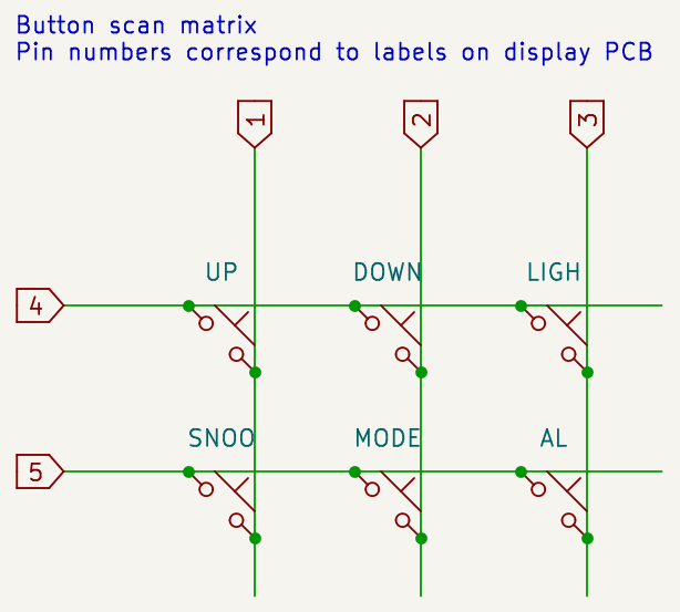
The button PCB with the label DIY-1941K contains 6 push buttons which are arranged into a small scan matrix. I traced the connections of the PCB
from photos and this is what I came up with:
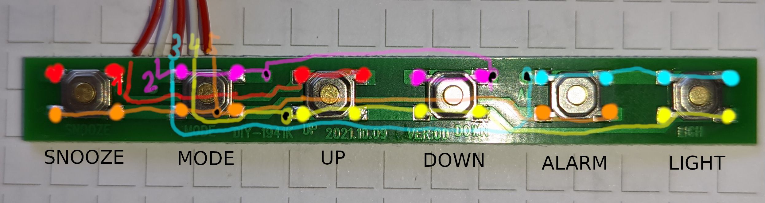
Which leads to the following schematic:
Power Supply #
The power supply board has labels DIY-1941C/LZX16-1001 V1.1 and does multiple jobs:
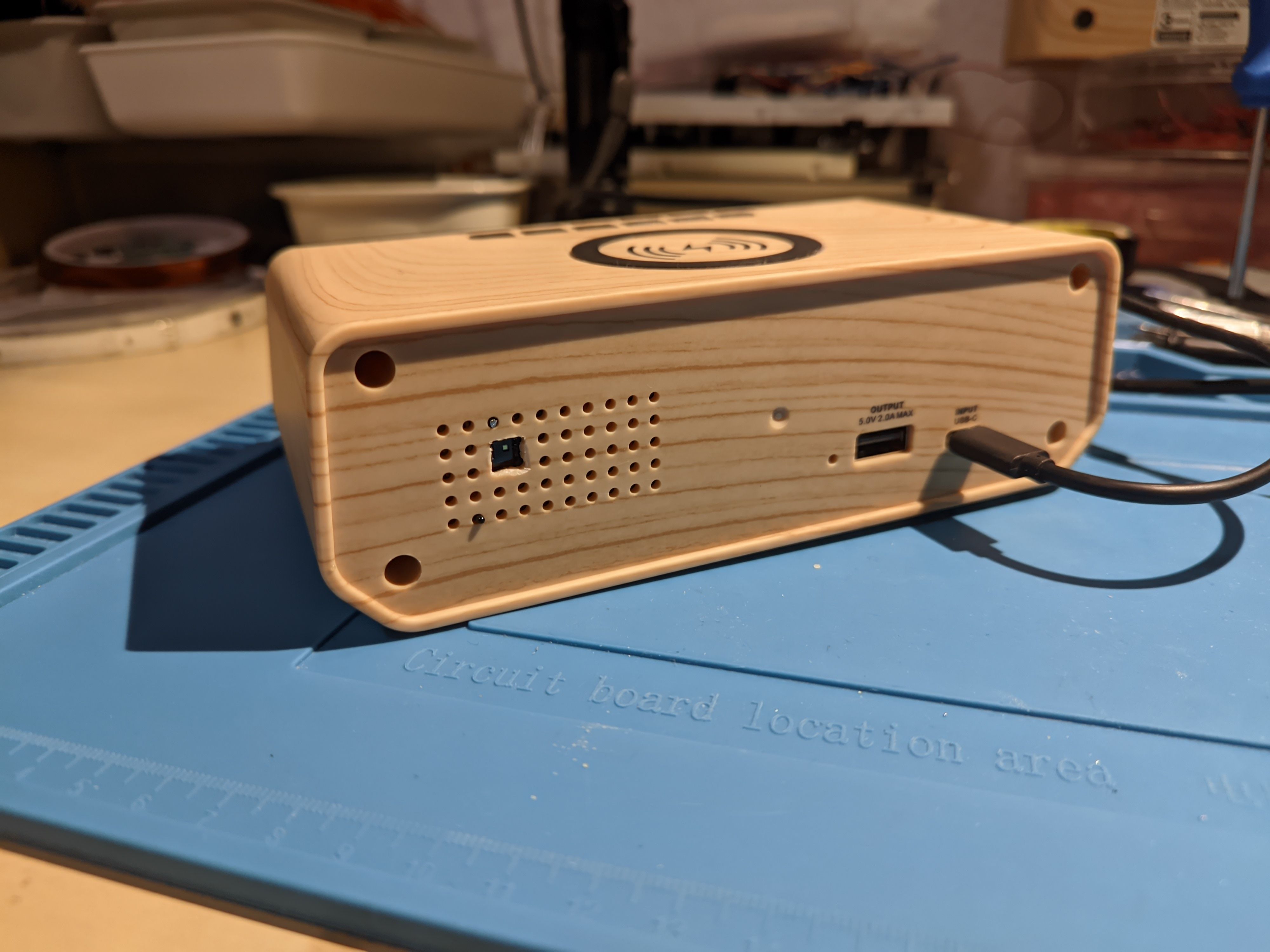
- A thermistor is located at the back of the clock which is connected by two wires to the supply board.
- On the back it has connections for a USB-C power input and a USB-A (5V/2A) power output.
- It controls the Qi wireless charging coil near the top of the clock.
- It connects to the display's main board with a 5 pin flex cable.
The easiest part are the 2 pins of the thermistor which are simply routed through to 2 pins of the display connector.
These pins are labelled RT+/-.
The USB-C's VBUS line goes to the wireless charging IC and to a switching regulator. I think there is some USB Power Delivery thing going on here where the input voltage isn't always 5V. The D+/D- data lines are connected to the IC but I didn't look into that further.
The switching regulator puts out 5 V which go to the USB-A socket and to the display connector.
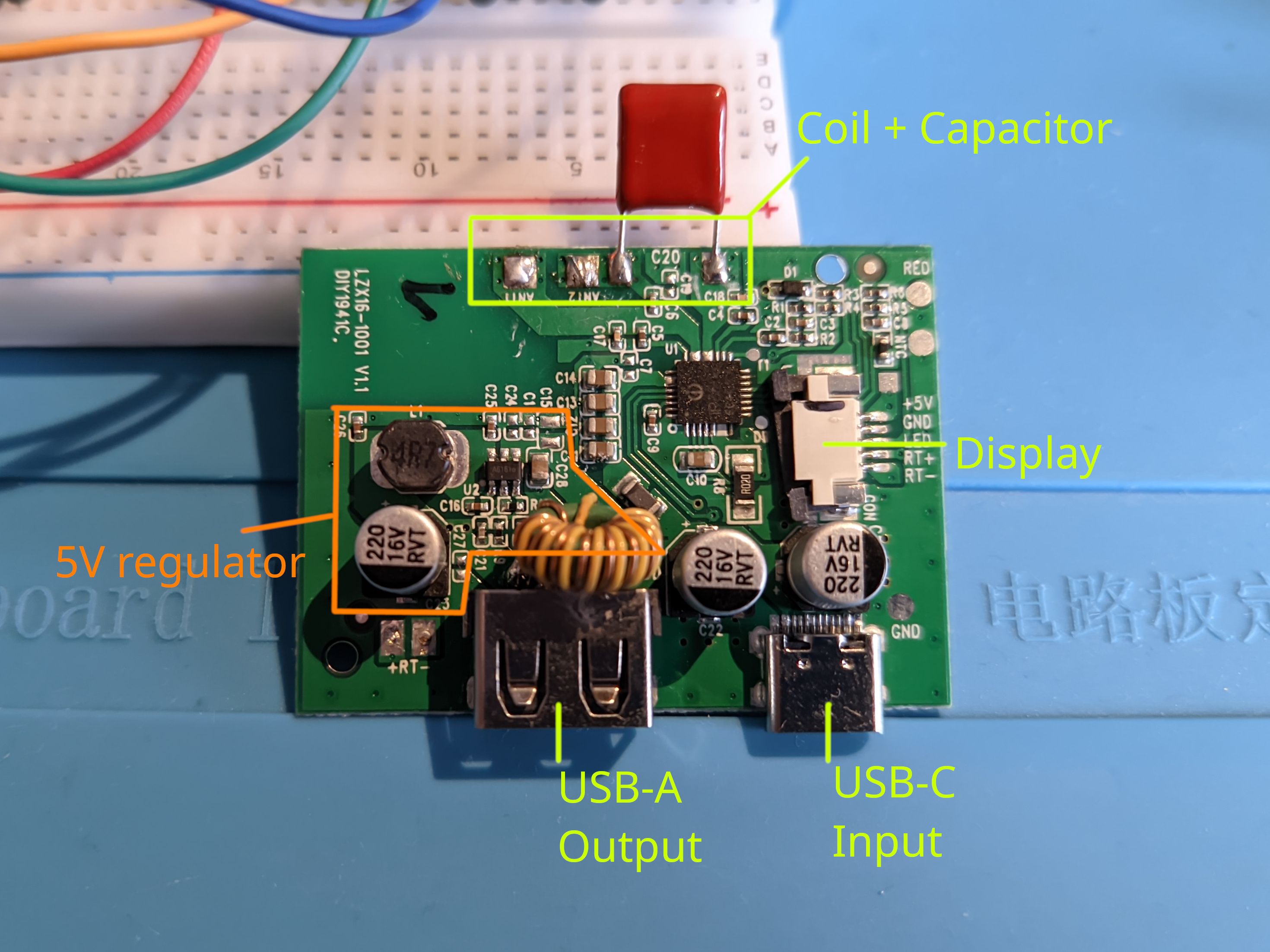
Most of the rest of the PCB is dedicated to the wireless charging feature around an Injoinic IP6806 (datasheet). It looks pretty similar to the Typical Application Schematic in section 6 of the datasheet. Except for the 3 possible LED outputs of which only LED1 is used which goes to the display connector as we already saw above.
Side note: The IP6806 has a thermal shutdown feature (datasheet, p. 8) using an NTC. But they put the NTC next to the display connector on the PCB in a seemingly useless position. I would have assumed that it should be measuring the parts with the most power losses like probably the H bridge in the charging IC or the charging coil.
Hardware Modifications #
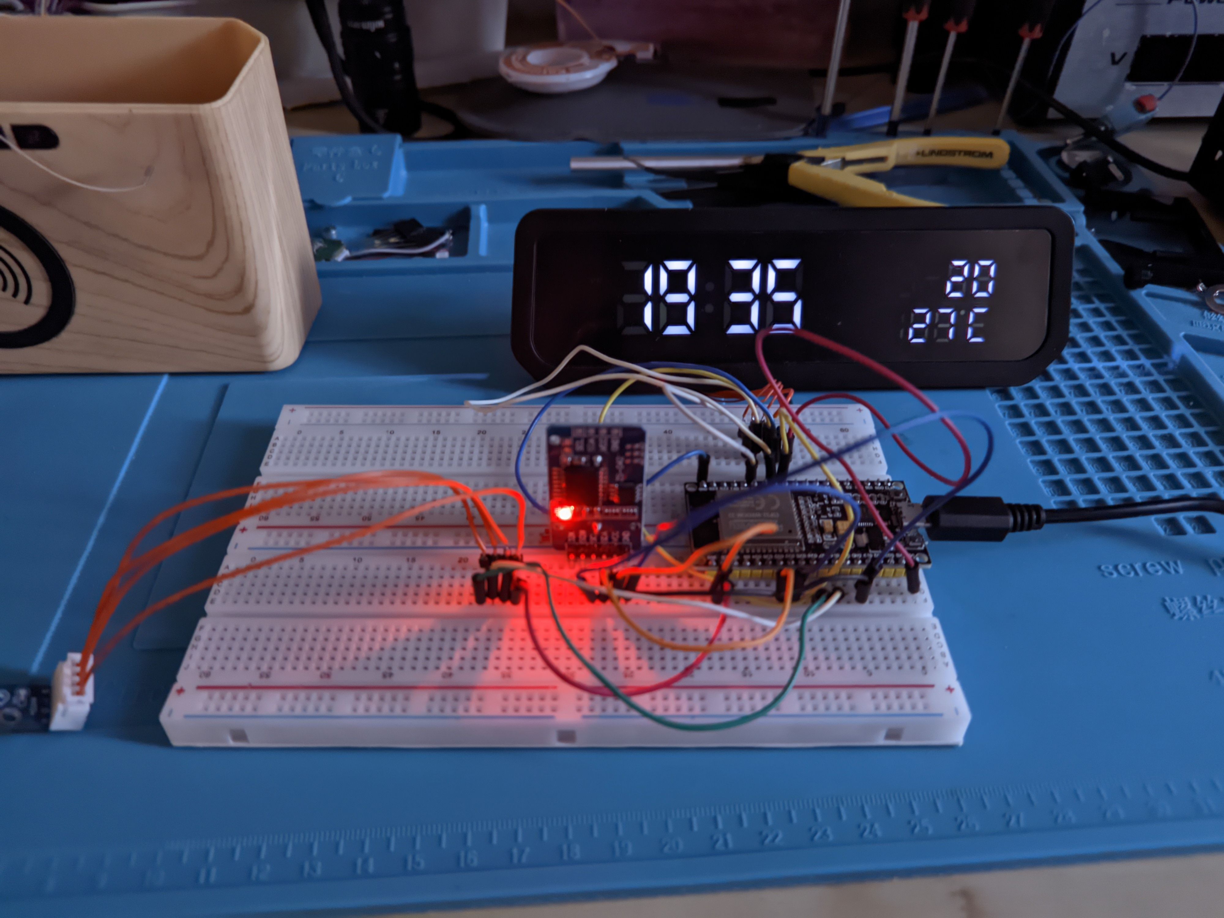
The goal of my modifications is to control the display from a custom ESP32 board so I can get features like NTP time synchronization and better display modes (e.g. night mode, events from and temperature/humidity reporting to HomeAssistant).
Also I want to remove wireless charging because I don't need it and in fact think it's quite annoying that the bolt symbol LED keeps blinking if I put something on top of the clock because of the foreign object detection.
Display Board Mods #
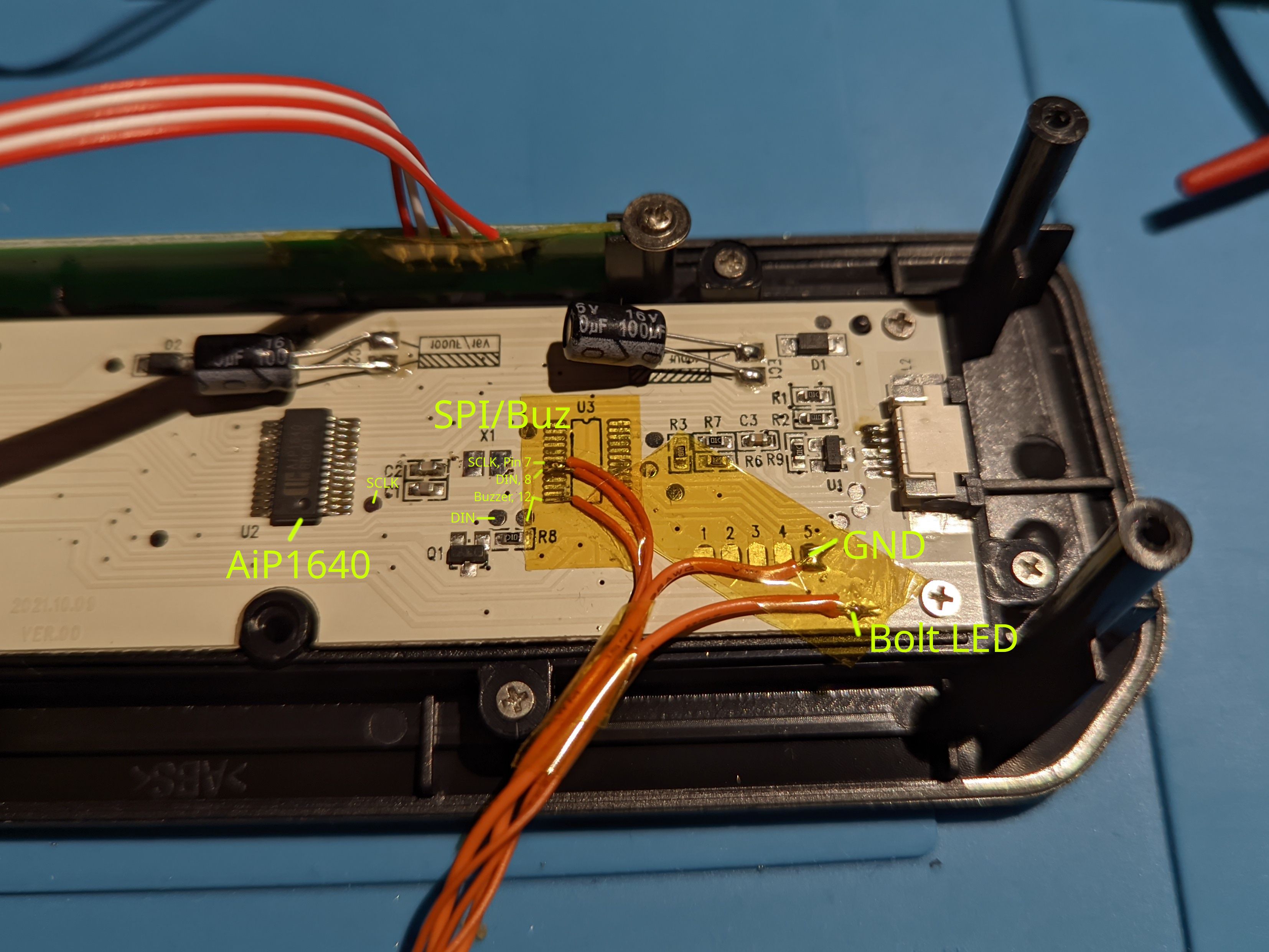
- I unsoldered the nameless microcontroller to get access to the two SPI pins (
DIN/SCLK) of the display controller and the buzzer driver. Those signals now go through a cable to my ESP32 board. - I also connected cables to Ground and the anode of the bolt LED.
- I salvaged the 32 kHz crystal and the coin cell holder.
- I unsoldered the button cables, extended them and put a connector on it for my board.
- Also after taking the photos I shortened the legs of the two electrolytic capacitors.
- Note that while I attached DIN, SCLK and BUZ to the microcontroller's pads I later noticed that you can more easily use test pads instead which are marked in the image above.

Power Supply Board Mods #
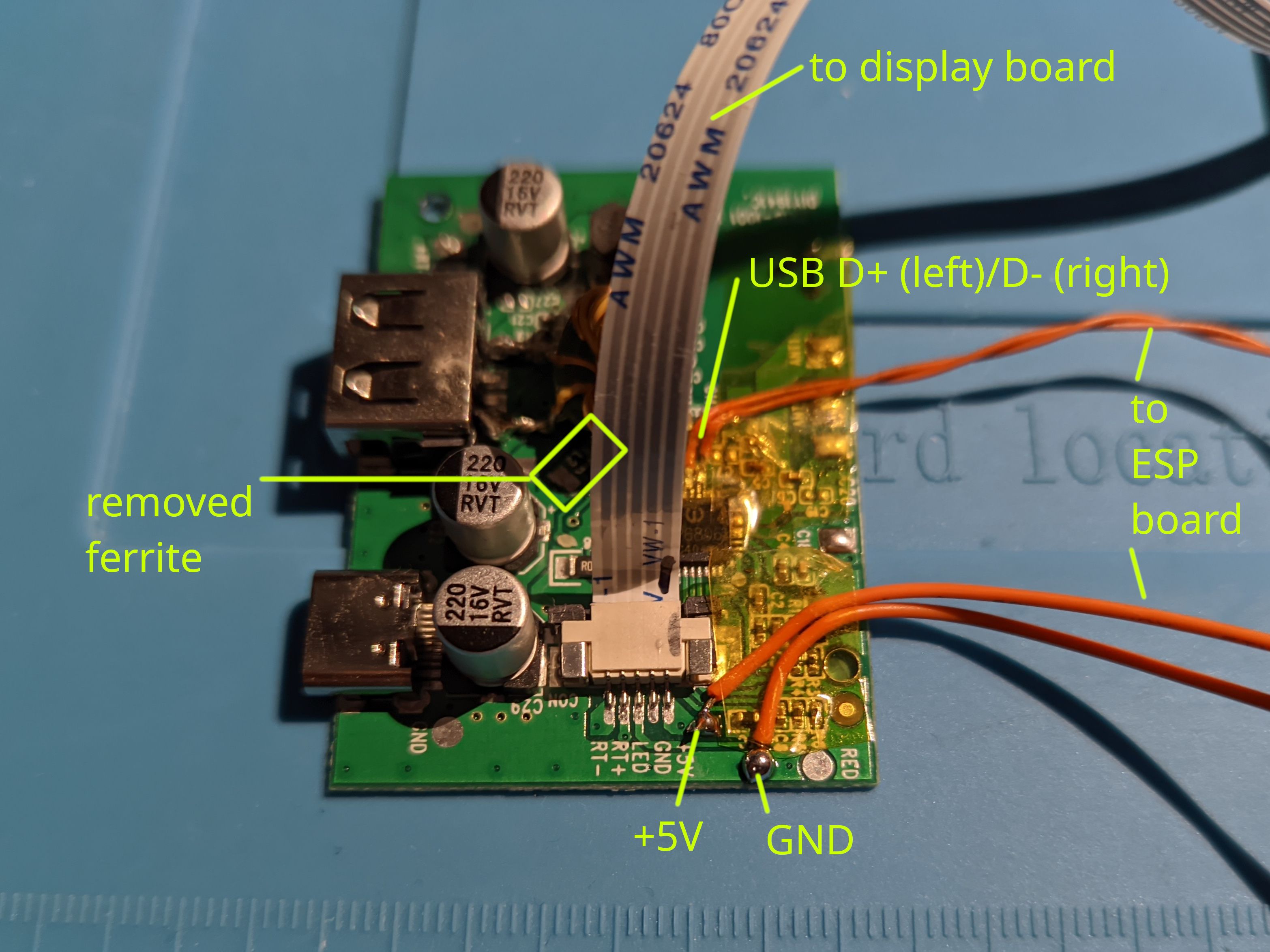
- I removed the big coil and capacitor so I have more space for my ESP32 board. I hoped that the
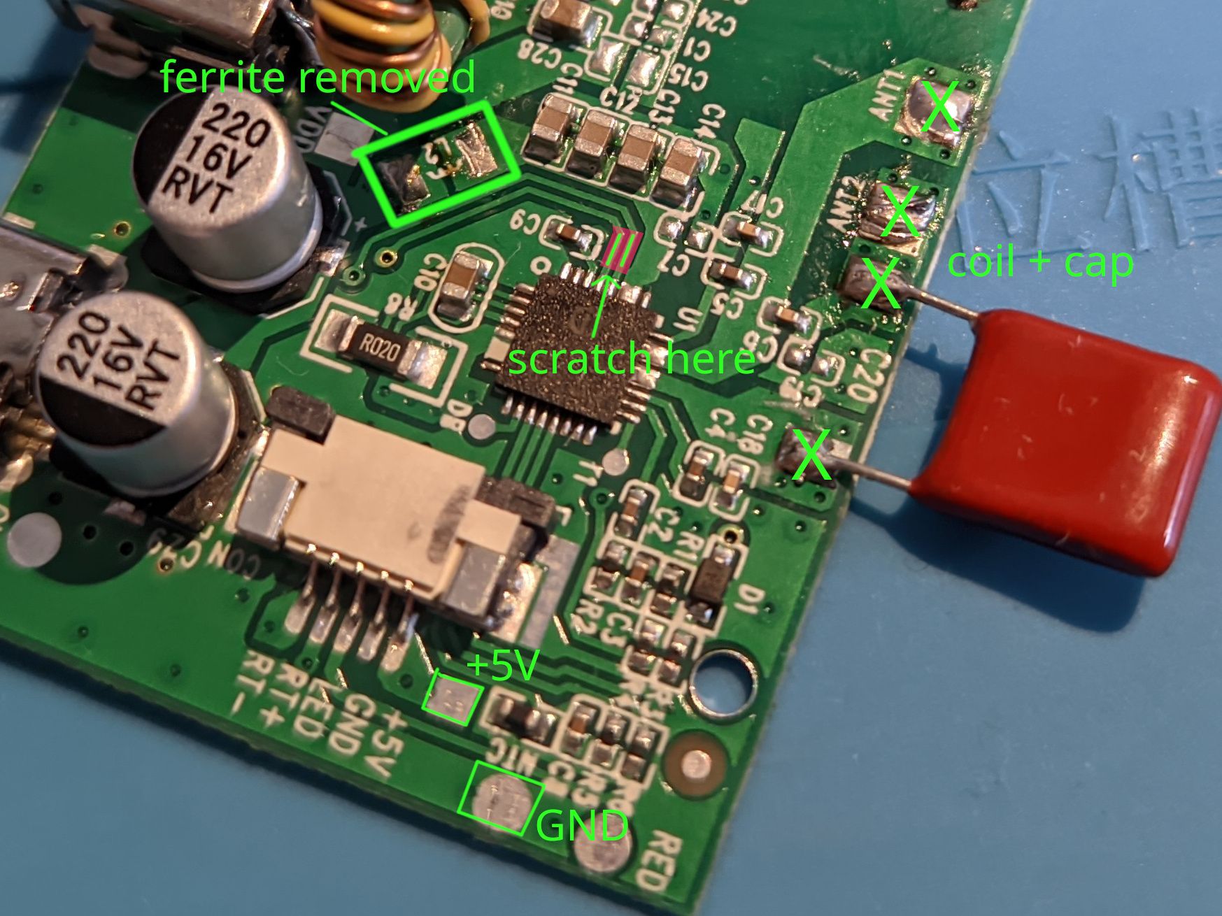
IP6806would detect the open lines and shut down but probing with an oscilloscope I found that it still puts a 100-something kHz square signal on the coil pads. - Thus not wanting to create unnecessary RF emissions I unsoldered the 1206-sized ferrite to cut power to the charging IC. The ferrite sits between USB-C VBUS and the IC and removing it doesn't affect the 5V switching regulator which powers our display and the USB-A port.
- With the
IP6806now completely disabled I scratched the solder resist off the USB-C connector's D+/D- traces and soldered tiny 32 AWG wires to them which go to the USB-UART converter on my ESP32 board. To my surprise this just worked and now I can flash the ESP32 using the USB-C socket.
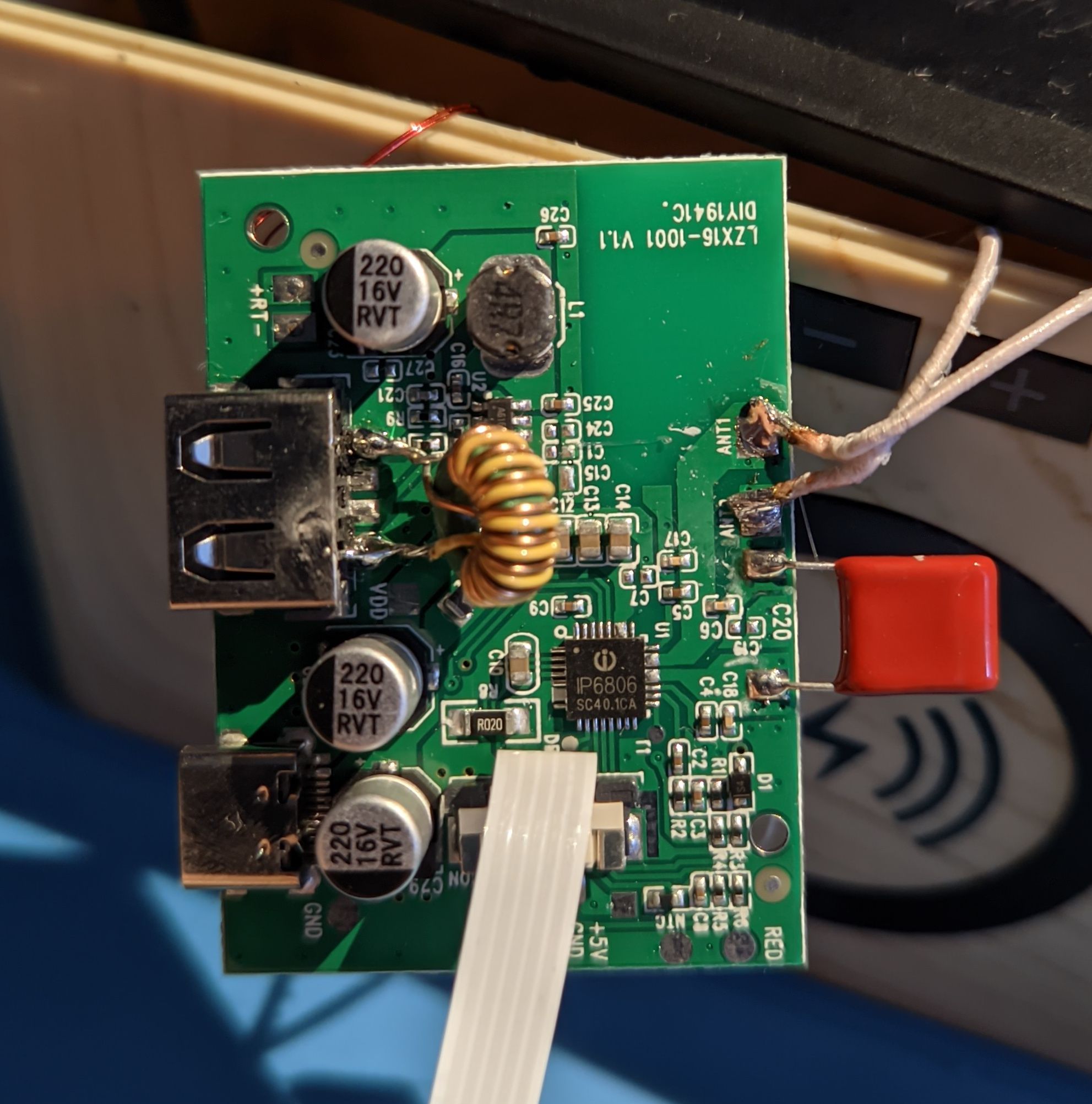
Here a close-up of the mods:
ESP32 Board #
Here is the schematic of my perfboard:
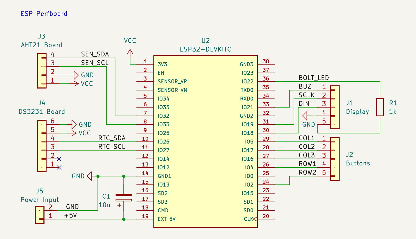
The board looks like this:
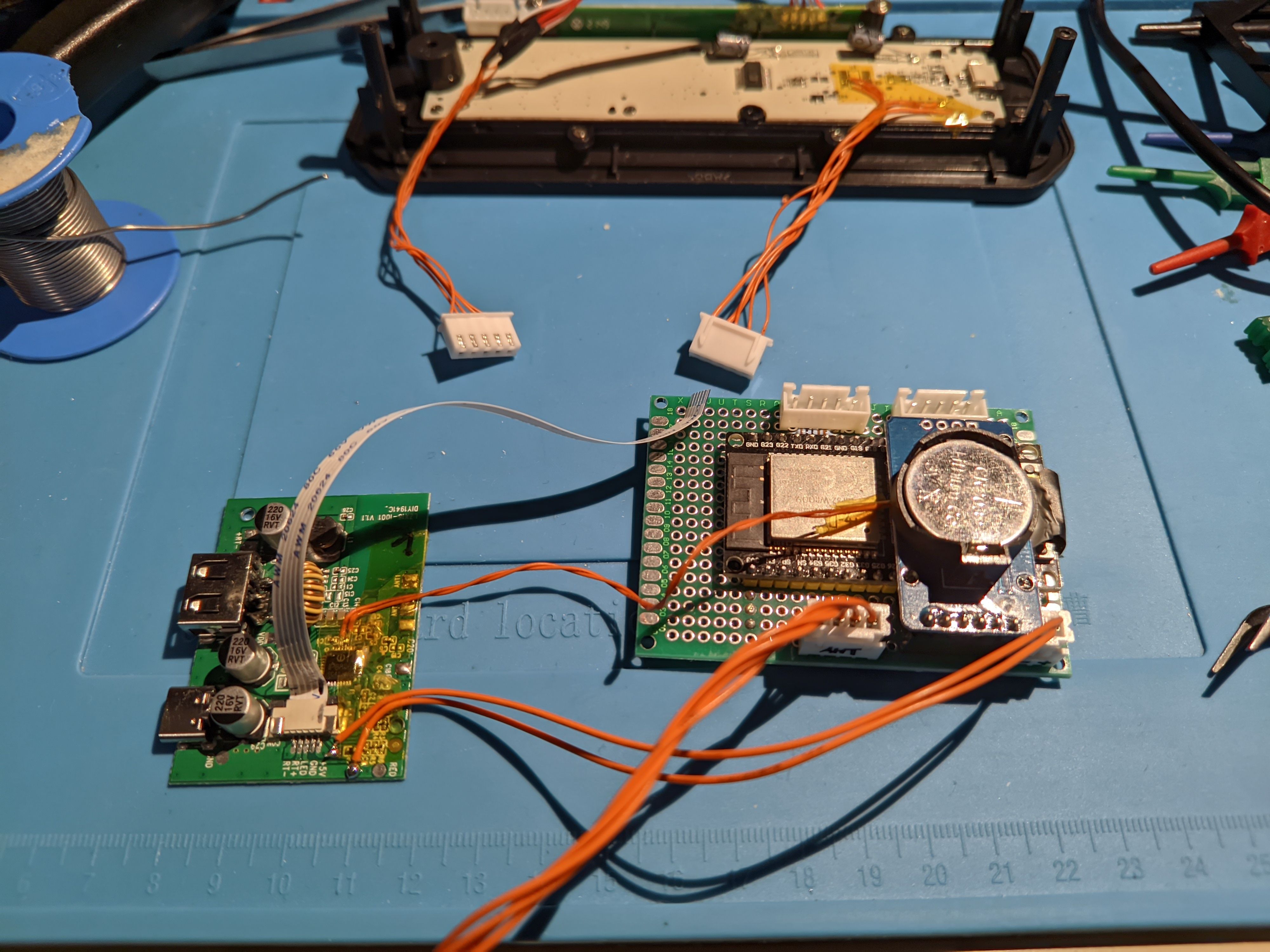
It consists of a bunch of standard components:
- ESP32 board with CP2102 USB-serial IC
- DS3231 RTC with I2C. Note that you'll have to remove a resistor when using this board with a non-rechargeable coin cell.
- AHT21 temperature/humidity sensor with I2C.
- 1 kΩ resistor for our special bolt LED
- 10-µF-or-so electrolytic capacitor
You can find KiCAD schematics in my repository.
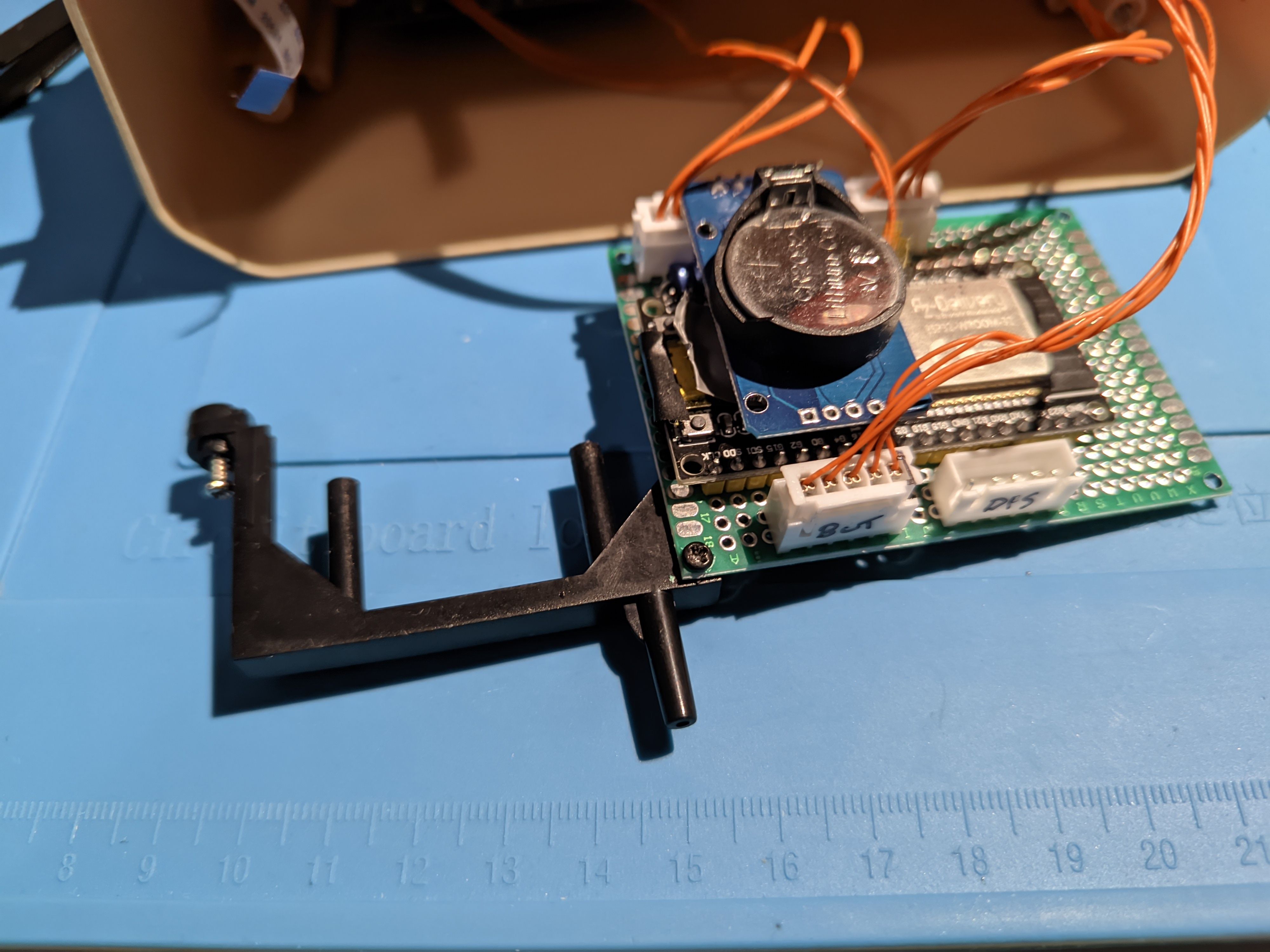
I screwed the perfboard to the plastic frame holding the power supply board using a self-tapping M2 screw. This is already pretty stable but for good measure I put in some foam to rest the right side of the board on.

The black plastic frame looks a bit twisted on the picture but it's actually held in place really solidly through the round pin which creates a bridge to the display unit when put together.
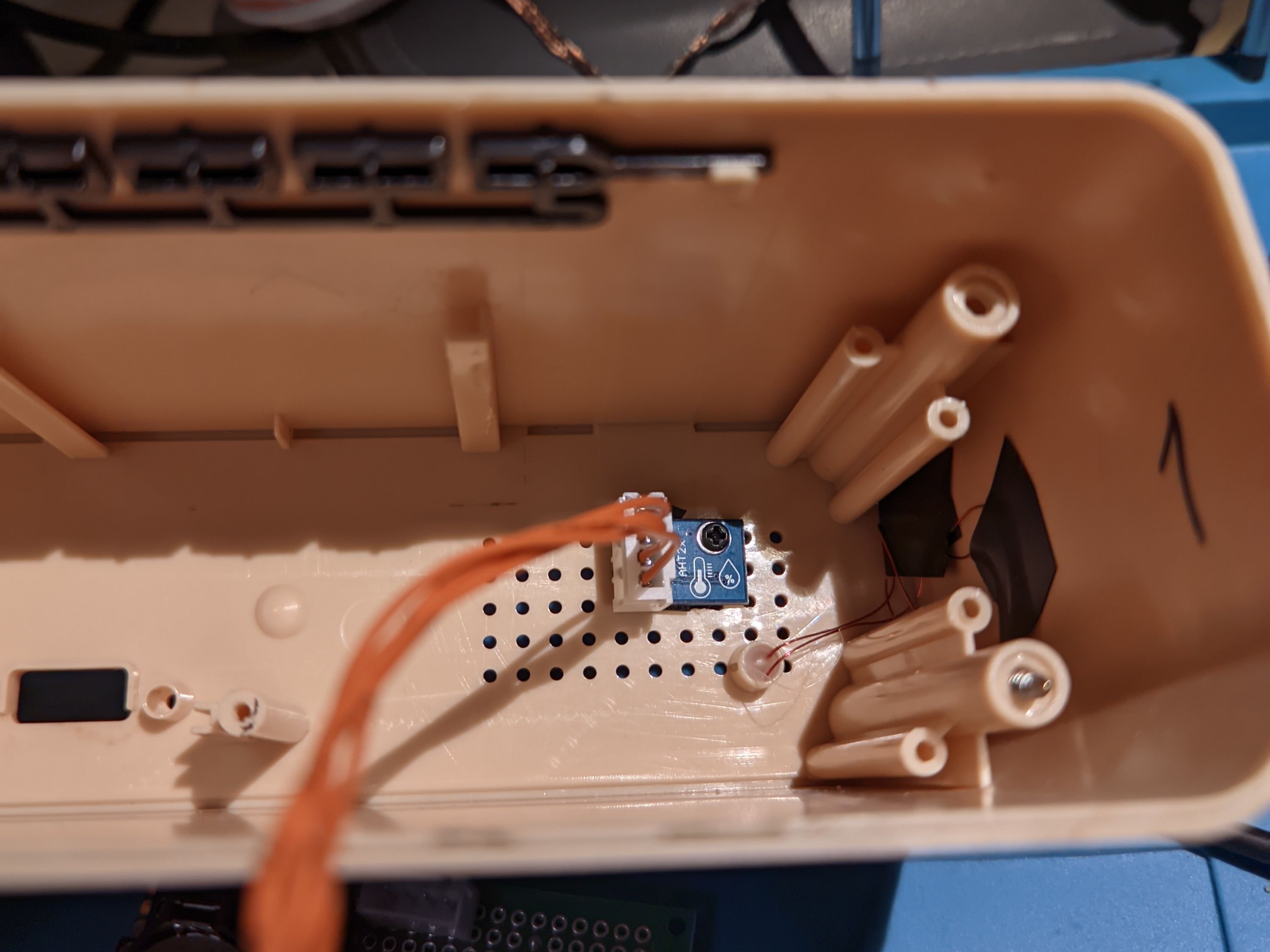
For the temperature/humidity sensor I made a small cutout at the back so it touches outside air. That board is also attached using a self-tapping M2 screw in an existing hole.
Software #
I used ESPHome for this project to simplify integration into HomeAssistant. realthk noted in an issue that he implemented TM1640 support based on ESPHome's TM1637 code and it works pretty well with the AiP1640 on this clock.
Some special handling for all the symbols and pseudo-segments on the display needed to be added. The rest is pretty much writing an ESPHome configuration.
Source code of my project can be found at: https://github.com/spezifisch/esp32-acqi-clock. To build and flash it you can use ESPHome's build instructions.
The first things I added was playing the mario theme using the RTTTL module of ESPHome and add a very low light night mode for the clock without blinking dots:

And of course a mode to show humidity which we can now measure, too:
The software is still work in progress but basic clock display works and I can use it on my night stand. My next steps will be modding the other clock and I think it should be possible to use the ESP32's hardware SPI instead of the bit-banging implementation in the current TM1640 module.
- Next: PSV3 Soldering Iron Hack - Part 1
- Previous: Pokemon Go Plus autocatcher DIY